MN003109A01_aa
2-44 Standard Configurations Speaker
4. Put the control head face down on a clean, flat surface to avoid damaging it. Do not touch the
o-ring on the back housing.
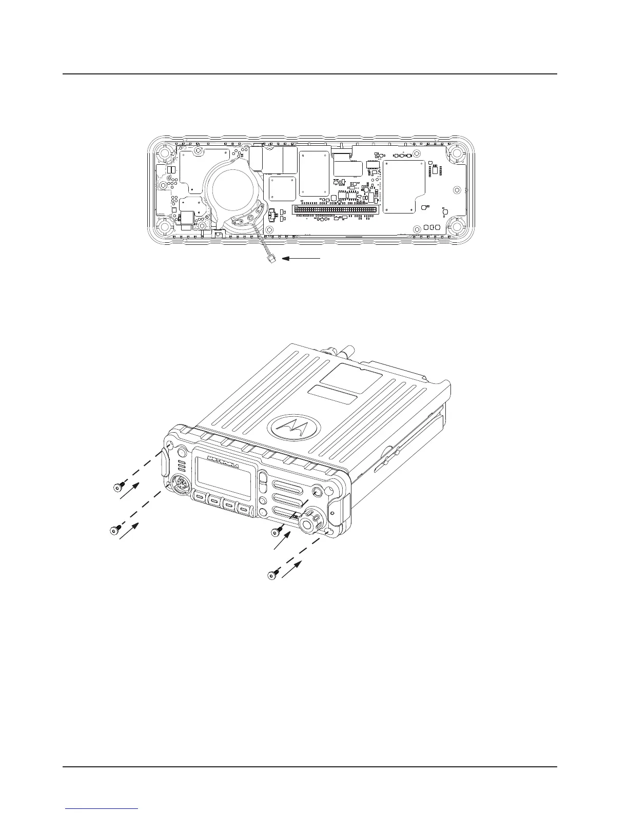
5. Carefully disconnect the speaker connector from the circuit board as shown in Figure 2-52.
Figure 2-52. Disconnecting the Speaker Connector
6. Reattach the front housing assembly to the back housing assembly as shown in Figure 2-53.
Make sure that the flex is returned to its original position and that the o-ring on the back
housing assembly is not pinched.
Figure 2-53. Reattaching the Control Head
7. Secure the front housing assembly back to the back housing assembly with four new screws
using the Torx T-20 bit as shown in Figure 2-53. Apply 9 in. lbs. torque for each screw.
The followings are the procedure to disassemble your radio for high power radios:
1. Remove the O2 Control Head front housing assembly. Refer to the APX8500 HP Basic
Service Manual (Add APX8500 HP Basic Service ManualP/N).
2. Put the control head face down on a clean, flat surface to avoid damaging it. Do not touch the
o-ring on the back housing.
3. Carefully disconnect the speaker connector from the circuit board as shown in Figure 2-52.
Draft

 Loading...


