AP_CMM2 User Manual Pa
e 9 of 49
GPS Status ......................................................................................................................................... 44
Ethernet Stats ..................................................................................................................................... 44
Expanded Stats................................................................................................................................... 45
ACCESSORIES ................................................................................................... 46
APPENDIX ........................................................................................................... 47
SPECIFICATIONS ............................................................................................... 48
Access Point Module.......................................................................................................................... 48
Cluster Management Module Gen II.................................................................................................. 49
Physical............................................................................................................................................... 49
AC Power ............................................................................................................................................ 49
DC Power (24V).................................................................................................................................. 49
DC Power (12V).................................................................................................................................. 49
Cable Specifications ........................................................................................................................... 49
TABLE OF FIGURES
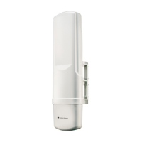
Figure 1: Canopy Access Point Module ................................................................................................ 11
Figure 2: Front view of Cluster Management Module, Installed........................................................... 12
Figure 3: Bottom view of Cluster Management Module, Installed........................................................ 13
Figure 4: System Wiring Diagram.......................................................................................................... 16
Figure 5: Fresnel Zone........................................................................................................................... 17
Figure 6: Laying out multiple Access Point clusters ............................................................................. 19
Figure 7: Location of 115/230 V Switch................................................................................................. 26
Figure 8: Detail of pole mounting........................................................................................................... 27
Figure 9: Detail of GPS antenna mounting ........................................................................................... 28
Figure 10: Port indicator LED on Ethernet switch................................................................................. 29
Figure 11: Quick Start web page ........................................................................................................... 32
Figure 12: Status web page ................................................................................................................... 33
Figure 13: Configuration web page ....................................................................................................... 35
Figure 14: LUID Select web page.......................................................................................................... 40
Figure 15: Link Test web page .............................................................................................................. 41

 Loading...