OVERVIEW: Digital Section
1.6.10 Battery ID
The battery is equipped with a Dallas 2502 EPROM. A two-wire serial bus allows the
i897 unit or the battery charger to communicate with the battery and identify whether or not
the battery is compatible. If the battery is determined to be incompatible, the charger does
not enter charging mode.
Besides compatibility data, the EPROM also stores such information as the battery type,
capacity, fuel-gauging parameters, and voltage thresholds.
1.6.11 Keypad Block
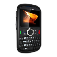
The MCU is responsible for decoding key presses and displaying them properly on the LCD. The
keys are arranged into a matrix of five rows and seven columns, which includes the Volume
buttons.
Athens Key Pad Matrix is formed by Zeus Key Pad port, ED_INT5 for PTT button, Pin R27- GP_AP_B2
for LOCK_SW; and a capacitance sense touch key pad matrix IC. The ON/OFF key is connected directly to Road
Runner.
COLUMN0 COLUMN3 COLUMN4COLUMN1 COLUMN2 COLUMN5 COLUMN6
ROW0
SEND SOFT_LEFT MENU SOFT_RIGHT Spare
LEFT_
ARROW
Spare
ROW1
* 7 4 1 SPARE
RIGHT_
Spare
ARROW
ROW2
0 8 5 2
UP_
Spare Spare
ARROW
ROW3
# 9 6 3
DOWN_
SPARE Spare
ARROW
Boost Live
Switch
ROW4
HI/LOW VOL_DOWN VOL_UP OK
Special Function
key/SMART
Spare
Table 1-4. Zeus Keypad Matrix
The On/Off button is not decoded by the MCU; it directly drives the ROADRUNNER, which
sends a signal to the MCU through INT1.
The On/Off key has been combined with the END and
Home. This key is NOT part of the matrix, as it needs to be connected directly to Roadrunner. Software
will monitor the duration of this key press to determine the function desired.
The five row lines are
pulled high through four internal 22- Kohm resistors. The five row lines and six column lines are
fed to ZEUS I/O pins. The PTT goes into ED_INT5 on Zeus.
Pin R27- GP_AP_B2 is connected for
LOCK_SW
The ZEUS de-bounces the keys by reading them 25 milliseconds later.
The keypad decoding scheme works as follows:
1. ZEUS sets the row pins to inputs; all columns pins are set as outputs and driven to logic
low.
2. Rows are pulled logic high. When a key is pressed, one row goes low, which
indicates a key press and sends an internal interrupt.
3. ZEUS reads rows. A low on that row indicates a key press. All others are high.
4. ZEUS sets all columns to output logic high.
One column at a time is set to output logic low. ZEUS reads the rows to see which one is
now at a logic low level. (A low seen on a row indicates the correct column and row.)

 Loading...


