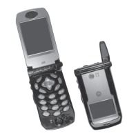
PREPARING FOR FIELD LEVEL TESTING: Dis-Assembly and Assembly of i897
2.5 Dis-Assembly and Assembly of i897 Unit
Motorola recommends the service technician follow a prescribed disassembly sequence to access
specific items or components of the unit. This product is an efficiently designed package that
incorporates the physical overlap and integration of some modular components. Refer to the
Disassembly Sequence Flowchart for a suggested path to reach specific components.
NOTE: In some cases, the technician may not need to remove certain components to reach
others.
2.6 Disassembly Procedure
NOTE: Screws used to assemble the i897 main housing are: 1 antenna screw, T-4 drive; 4 housing assembly
screws, T-6 drive.
2.6.1 Disassembly Sequence Pane chart
Note: i897 flip components include a Flex Connector ribbon which can be easily torn or damaged if not
handled properly. Handle the Flex Ribbon with care especially when working it through the front housing
slot.
Main Board
Antennas
Back Housing
Front Housing
Battery Cover
SIM Card
Battery
USB Cover
Flip Assembly
SD Card
Battery Frame

 Loading...