3-2 Hardware Tuning Setup and Procedure
2.0 Hardware Tuning Setup and Procedure
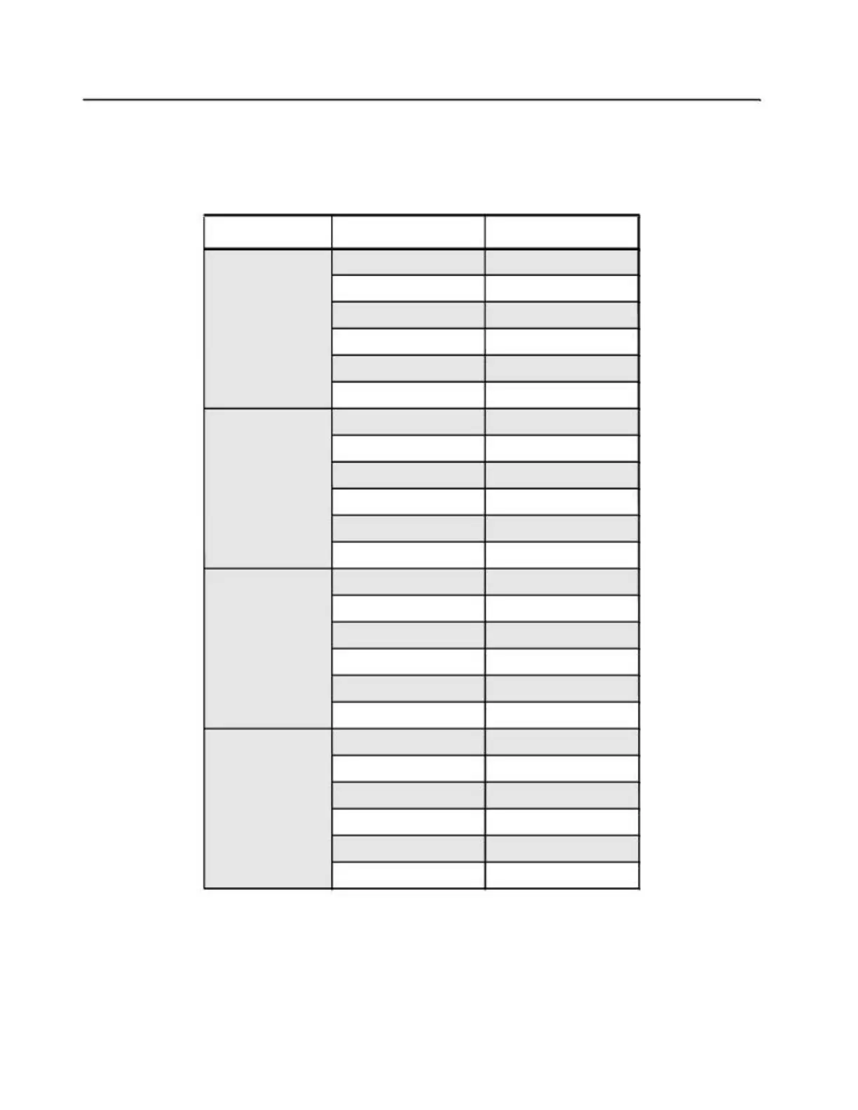
2.1 Tuning Frequency
Table 3-1 Frequencies Used for Tuning.
Band Tuning Parameter Frequency (MHz)
PLL Synthesizer 149.975
Transmitter 136.025
Receiver 136.025
VHF 136 - 150 MHz
Modulation Balance 136.025 (N band)
Sub-Tone Modulation 149.975 (S band)
Maximum Modulation 149.975 (S band)
PLL Synthesizer 173.975
Transmitter 150.025
Receiver 150.025
VHF 150 - 174 MHz
Modulation Balance 150.025 (N band)
Sub-Tone Modulation 173.975 (S band)
Maximum Modulation 173.975 (S band)
PLL Synthesizer 424.975
Transmitter 403.025
Receiver 403.025
UHF 403 - 425 MHz
Modulation Balance 424.975(N band)
Sub-Tone Modulation 403.025(N band)
Maximum Modulation 403.025(N band)
PLL Synthesizer 469.975
Transmitter 450.025
Receiver 450.025
UHF 450 - 470 MHz
Modulation Balance 469.975(N band)
Sub-Tone Modulation 450.025(N band)
Maximum Modulation 450.025(N band)
2.2 Preparation Before Tuning (refer to Figure 3-1)
1. Set Power Supply to 7.5V and then connect to the radio.
2. Connect the connector and ground plate to the radio antenna port.
 Loading...