2-8 Radio Reassembly — Detailed
6.2 PC Board Disassembly
1. Remove the audio jack seal.
2. Remove the 10 screws which hold the PC board to the diecast.
3. Next, remove the 2 nuts on the On/Off Volume and Channel knobs shafts with the Crab Eye
Nut Opener.
4. The PC board can now be removed from the rear diecast.
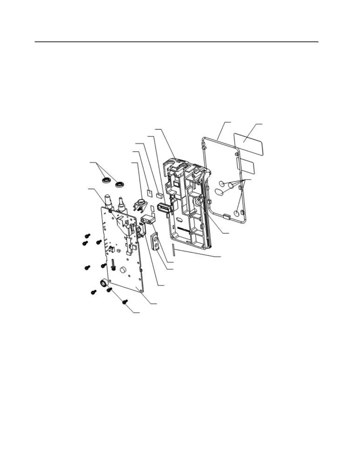
5. The completely disassembly PC board is shown in “Figure 2-7”.
O-ring
Tanapa Label
Radio Chasis
POGO Pin Seal
Thermal Pad
PTT Insulation Tape
Crab-eye Knob Nut
Antenna Bracket
Stickers for
Tuning Holes
Shield
Thermal Paste
PCB-Chassis Tape
POGO Pin Housing
Audio Jack Seal
Audio Bracket
PCB
Microphone Boot
Figure 2-7 Completely Disassembled PC Board
7.0 Radio Reassembly — Detailed
7.1 PC Board Reassembly
1. Place the PC board on the rear diecast.
2. Tighten the screws and the nuts on the two knobs.
3. Replace the audio jack seal.
 Loading...