December 2, 2003 6881096C46-O
6-4 Installation, Disassembly, and Assembly: Horn-Ring Transfer Relay
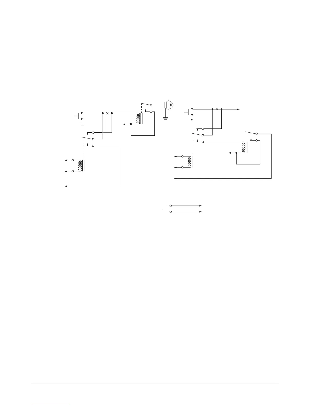
6.2 Horn-Ring Transfer Relay
In order to make Siren operation more convenient under emergency conditions, the vehicle’s Horn-
Ring (or buttons) can be used to control siren functions (refer to Chapter 2 on page 2-2). This
convenience allows the driver to concentrate on the road and traffic conditions.
Figure 6-4 shows wiring diagrams for connecting the Horn-Ring via a transfer relay for both negative
and positive ground systems. As an alternative, a simple momentary contact pushbutton (normally
open) may be installed in the vehicle, in a location convenient to the driver.
Figure 6-4: Siren/PA Horn-Ring Connections
6.3 Disassembly and Assembly
Item numbers in parentheses refer to parts identified in Figure 8-6, on page 8-9 in Chapter 8 of this
manual.
6.3.1 Disassembly
1. Place the Siren/PA on a workbench with the top cover (2) upward. Loosen four screws (1)
and remove the top cover (2) from the chassis (8).
2. Remove the component side shield cover (27) by prying the corners from the shield fence
(28) and lifting upward.
3. Remove the main PC board as follows:
a. Remove the screw (29) near the connector (11).
b. Remove the screw (12) and bracket (13) that attach the bus assembly (14).
c. Remove two screws (15) from either side of the PC board (16).
To Horn
Break
Here
Horn
Ring
To Control Head VIP
Output Programmed for
Horn-Ring Transfer
To SW B+ at
VIP Connector
To Control Head VIP
Input Programmed
for Horn-Ring
N.C.
COM.
N.O.
To DIG. GND at
VIP Connector
+ 12V
Positive-Contact Horn-Ring
Negative-Contact Horn-Ring
Under Hood
Horn Relay
Horn
Break
Here
Horn
Ring
To Control Head VIP
Output Programmed for
Horn-Ring Transfer
To SW B+ at
VIP Connector
To Control Head VIP
Input Programmed
for Horn-Ring
Any SPDT Relay with 12V Coil
and Suitable Contact Ratings for
Vehicle Installation
N.C.
COM.
N.O.
+ 12V
Normally-Open
Momentary
Contact Pushbutton
To VIP Input Programmed for Horn-Ring
To DIG. GND at VIP Connector
Pushbutton Connections
NOTE: Locate Pushbutton
in a Location Convenient to
the Driver
MAEPF-26792-O

 Loading...


