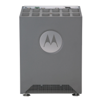
RFS4010 RF Switch: Installation Guide
20
3. As soon as the switch resets, depress the reset button on the rear of the switch and continue
to hold it through the boot up process until the following message is displayed in the
console:
Startup config will be RESET to factory default
loading linux image 2 .......................
Welcome to RFS4000
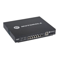
4.8 Verifying the Installation
View the LEDs on the front panel of the RFS4010 RF Switch to ensure the device is functioning
properly. The normal LED pattern follows this path:
• During the Power On Self Test (POST), the System 1 and System 2 LEDs both blink green.
• If the POST test fails, the System 1 LED will blink amber. If the POST test succeeds, the System
1 LED will be lit solid green.
• As the software is initialized, the System 2 LED will blink green.
• After the software has finished initializing, the System 1 LED will be lit solid green and the
bottom System 2 LED will be off. The RFS4010 RF Switch is ready to be configured, as described
in the RFS Series Wireless LAN Switches WiNG System Reference Guide.
Other LED codes indicate the presence (or absence) of different standby states, or errors. A guide to
the RFS4010 RF Switch LEDs codes is provided in Chapter 3, LED Codes.
CAUTION Using the switch reset button will reset all configuration information
and settings on the switch to factory defaults. All previously
configured information and settings will be lost. The country code will
need to be set when the switch is rebooted before any Access Ports or
Adaptive APs will be adopted.
 Loading...