28 September 30, 2003 6809468A80
Disassembly V300/V500
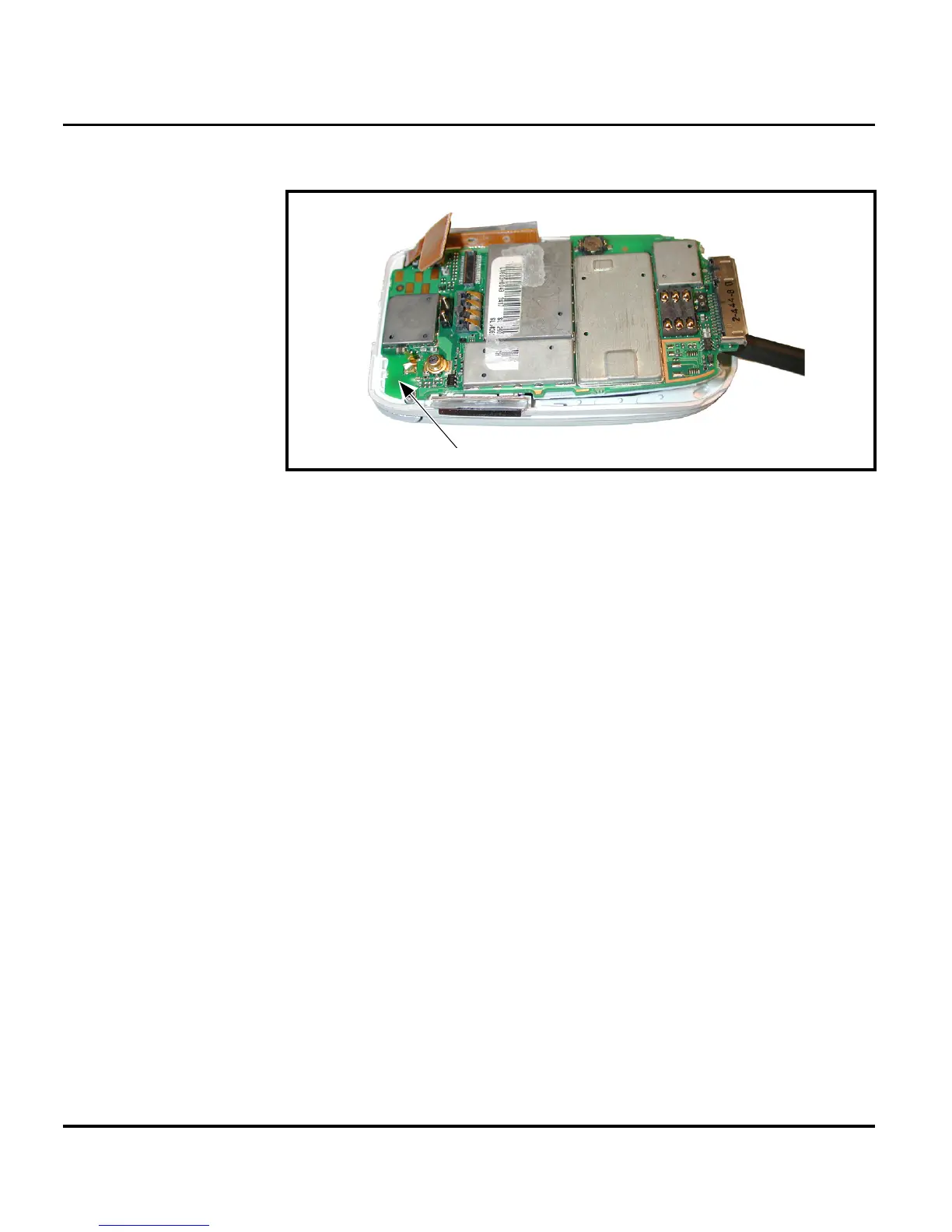
3. Lift the transceiver board assembly out of the front housing. See Figure 9.
4. To replace, insert the transceiver board assembly into the front housing with
the flex connector on top.
5. Insert the flex connector squarely into its mating connector on the transceiver
board and press firmly until it snaps into place.
6. Replace the rear housing, antenna, SIM, battery, and battery cover as
described in the procedures.
031641o
Figure 9. Removing the transceiver PC board assembly
➧
Be sure the volume/smart buttons and voice button are correctly positioned in
relation to the corresponding switches on the transceiver board. Verify operation of
the buttons after replacing the transceiver board and rear chassis assembly.
Transceiver PCB Assembly
 Loading...