48 September 30, 2003 6809468A80
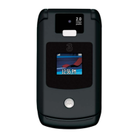
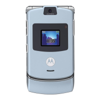
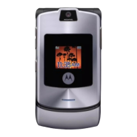
Troubleshooting V300/V500
Programming: Software Upgrade and Flexing
Contact your local technical support engineer for information about equipment and
procedures for flashing and flexing.
8. Phone does not sense when flip is
opened or closed (usually indicated by
inability to answer incoming calls by
opening the flip, or inability to make
outgoing calls).
a) Flip assembly defective. Temporarily replace the flip assembly with a
known good assembly. If fault has been cleared,
reassemble with the new flip assembly. If fault
not cleared, proceed to b.
b) Transceiver board assembly
defective.
Replace the transceiver board assembly (refer
to 1c). Verify that the fault has been cleared and
reassemble the unit with the new transceiver
board assembly.
9. Vibrator feature not functioning. Transceiver board assembly defective. Replace the transceiver board assembly (refer
to 1c). Verify that the fault has been cleared and
reassemble the unit with the new transceiver
board assembly.
10. Internal Charger not working. Faulty charger circuit on transceiver
board assembly.
Test a selection of batteries in the rear pocket of
the desktop charger. Check LED display for the
charging indications. If these are charging
properly, then the internal charger is at fault.
Replace the transceiver board assembly (refer
to 1c). Verify that the fault has been cleared and
reassemble the unit with the new transceiver
board assembly.
11. Real Time Clock resetting when
standard battery is removed.
Lithium button cell in the display board
may be depleted.
Refer service to a Level 3 service center for
replacement.
12. No or weak audio when using headset. a) Headset not fully pushed home. Ensure the headset plug is fully seated in the
connector socket. If fault not cleared, proceed to
b.
b) Faulty connector socket on
transceiver board assembly.
Replace the transceiver board assembly (refer
to 1c). Verify that the fault has been cleared and
reassemble the unit with the new transceiver
board assembly.
Table 4. V300 Telephone: Level 1 and 2 Troubleshooting Chart (Continued)
SYMPTOM PROBABLE CAUSE VERIFICATION AND REMEDY
 Loading...