Motorola Confidential Proprietary
Manual Test ProceduresLevel 3 Service Manual
2-3
Draft 1.0
9. Dial a number from the phone and press the
send button.
10. The phone is now connected.
Call Test Parameters (GSM/DCS/PCS)
While the phone under test is in an active call, the pa-
rameters for each band should be verified as described.
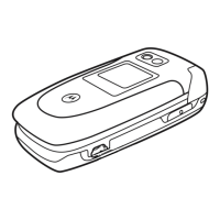
Figure 2-2. GSM Connection Control
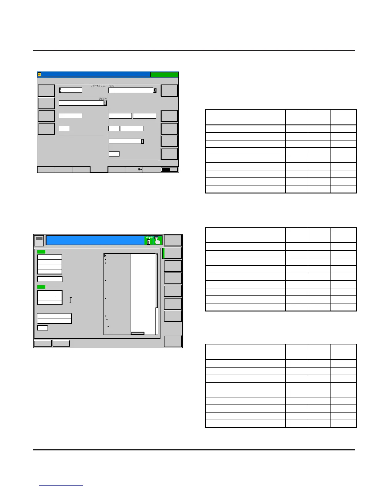
Figure 2-3. GSM Call Connected
Slot
Single Slot
GSM
Mode
TCH
Level
RF
Channel
Hopping
Timeslot
BS Signal
Signal On
Connection Control
900
- 20.0
dB
-85.0
dBm
925.2
MHz
975
Off
3
Frequency
Offset
Mode
BCCH
Level
RF
Channel
-85.0
dBm
+0
Hz
BCCHandTCH
37
used unused
MS SignalConnection SyncAF/RFNetwork 21
1(28.01(28.0
Appli-
cation
MS Signal
BS Signal
Network
Menus
dBm
Connect
Control
P/t Norm,
GMSK
ReportedPower
PCL
Analyzer
Level
)
dBm
25.5
dBm
25.7
Ok
Sym.
-0.75
Avg.BurstPower(Current)
Peak BurstPower
Power Ramp
TimeAdvanceError
Ext. Phase Error GMSK
Frequency Error
Peak PhaseError(Current)
RMS
MS Receiver Reports
RX Level
RXQuality
DiscontinuousTransmission(DTX)
Hz
-30
6.2
2.1
17
-94to -93dBm)(
(0.0to 0.2%)(
0
Off
P/t NormGMSK
R
U
N
Timing
Advance
Settings
SignallingStates
MS Capabililties
Signalling Info
IMSI
IMEI
Dialled Number
Traffic Mode
Meas. Control
Repetition
Stop Condition
DisplayMode
Statistic Count
AnalyzerLevel
RF Mode
RFAttenuation
TriigerSource
TriggerSlope
MS Signal
CIrcuitSwitched
TimingAdvance
SingleSlot
PCL (MS)
--- ------
--- ------ --
123655
Full Rate Version 1
Continuous
None
Current
100Bursts
Auto
LowNoise
Signalling
RisingEdge
0Sym.
1(28.0dBm)
RUN
RUN
1(28.0
GSM
1800 Overview
Ch. 2
Circuit
Switched
Single Slot
Ch. 1
¹Power Level = 5
²Set BS TCH level to -105 dBm
³Set BER TCH level to -105 dBm with 10k bits or 128 Frames
Table 2-1. GSM Call Parameters
¹Power Level = 15
²Set BS TCH level to -103 dBm
³Set BER TCH level to -103 dBm with 10k bits or 128 Frames
Table 2-2. DCS Call Parameters
¹Power Level = 15
²Set BS TCH level to -104 dBm
³Set BER TCH level to -104 dBm with 10k bits or 128 Frames
Table 2-3. PCS Call Parameters
Parameter
Low
Limit
High
Limit
Unit
Burst Avg Power Out¹ -5 5 dBm
Burst Output Shape 1 1 P/F
Time Advance Error -1 1 bit/sym
RMS Phase Error 0 5 deg
Peak Phase Error -20 20 deg
Frequency Error -190 190 Hz
RX Level Error@-104 dBm² 2 10
RX Quality @-104 dBm² 0 4
BER @-104, 10k bits³ 0 2 %
Parameter
Low
Limit
High
Limit
Unit
Burst Avg Power Out¹ -5 5 dBm
Burst Output Shape 1 1 P/F
Time Advance Error -1 1 bit/sym
RMS Phase Error 0 5 deg
Peak Phase Error -20 20 deg
Frequency Error -180 180 Hz
RX Level Error@-103 dBm² 3 11
RX Quality @-103 dBm² 0 4
BER @-103, 10k bits³ 0 2 %
Parameter
Low
Limit
High
Limit
Unit
Burst Avg Power Out¹ 27 31 dBm
Burst Output Shape 1 1 P/F
Time Advance Error -1 1 bit/sym
RMS Phase Error 0 5 deg
Peak Phase Error -20 20 deg
Frequency Error -90 90 Hz
RX Level Error@-105 dBm² 1 9
RX Quality @-105 dBm² 0 4
BER @-105, 10k bits³ 0 2 %
GSM/DCS/PCS Call Processing
 Loading...