Motorola Confidential Proprietary
V975/V980Theory of Operation
3-22
Draft 1.0
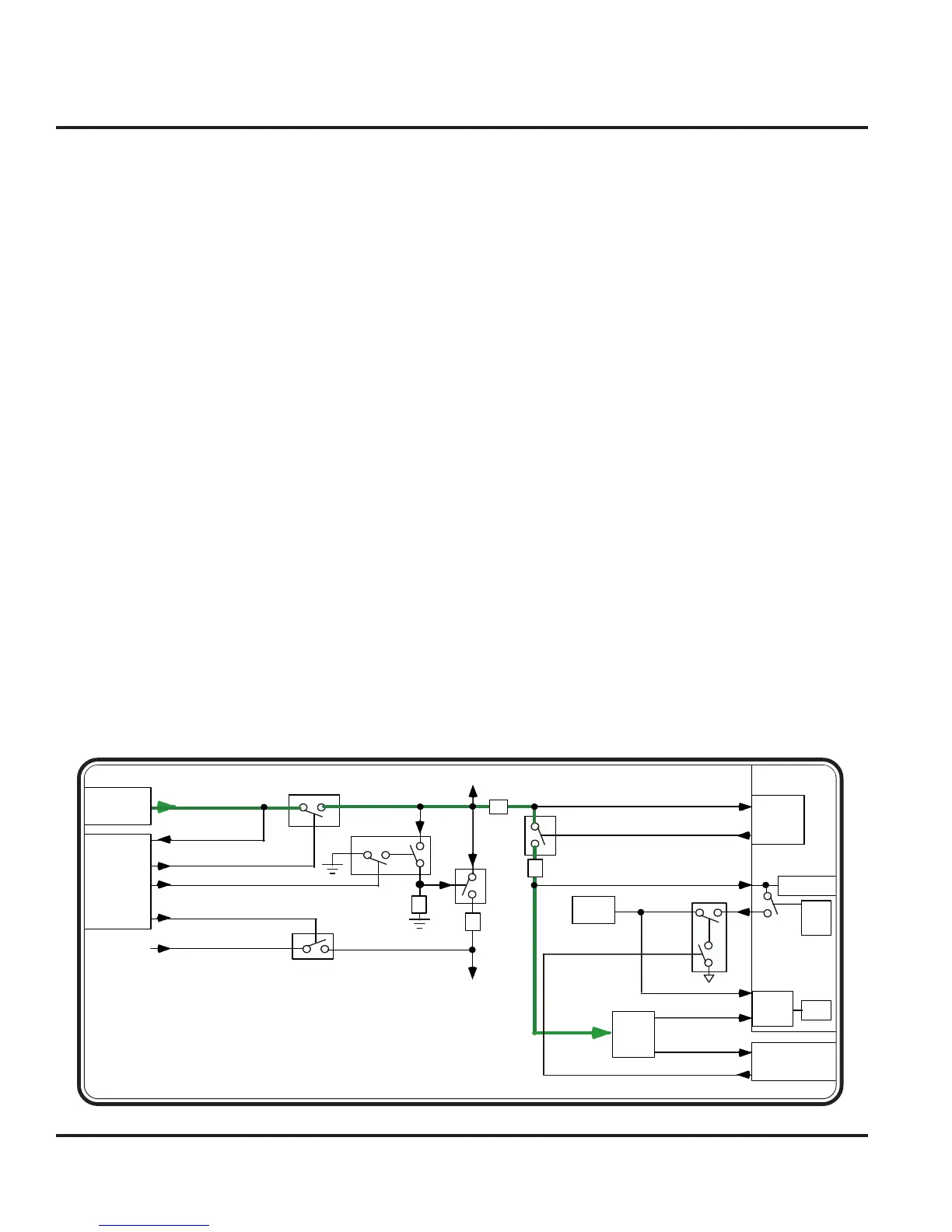
Battery Interface
Batteries interface to the main transceiver board via a
4-pin connector (J5400). Motorola approved remov-
able Lithium Ion and Lithium Polymer batteries are sup-
ported. Upon power-up, the MCU (through it’s inte-
grated One-Wire Interface Module) will interrogate the
EPROM located inside the battery package to deter-
mine battery characteristics that impact radio and charg-
ing operations. Battery validity will also be verified. A
thermistor element in the battery package provides tem-
perature feedback.
During normal phone operation, without a charger at-
tached, Q5400 is turned ON so that current can be
supplied from the battery to the B+ power node on the
transceiver board. When the phone is ‘ON’, the PCAP
IC (U3000) will enable its internal regulators so that
transceiver circuitry can be enabled. When the phone
is ‘OFF’, the PCAP IC disables its regulators to dis-
able most active circuitry. In the OFF state, only mini-
mal circuitry will be connected to B+ to minimize ‘OFF’
state leakage current.
Lithium Ion/Polymer charging is internally supported in
the phone. Full rate charging is supported when a valid
full rate charger is detected on the accessory interface
(J5000). During full rate charging, Q3966 is turned
ON so that current can be supplied from the external
source to B+. Q5400 will be turned OFF to discon-
nect the Battery from B+. Based on battery voltage
and radio status, charging current will be set by con-
trolling the voltage at the gate of Q3960. A sense resis-
tor (R3961) provides current sense feedback to the
charger circuit. Battery charging will be disabled if an
invalid battery is detected, if the radio is transmitting, if
temperature is too high or too low, or if the battery volt-
age is too high.
Reduced rate charging is supported when a compatible
lower capacity charger is detected on the accessory
interface (J5000). Operation with a reduced rate
charger will not allow dead battery or ‘no battery’ op-
eration.
RAW_EXT_B+
EXT_B+
B+
ISENSE
CHRGC
BATT+
MAIN_FET
BATT+
Q3966
Q3967
R5480
CR3961
R3961
Q3960
CR3960
Q5400
Q3963
OV_GATE
OV_SENSE
PCAP
U3000
MIDRATE_1
PCAP
U3000
CE
Conn
Charger
BATT_FDBK
AD6
BATT_THERM
CE
Conn
SPI
MUX
BattSense
BATT_IO
POG
Batt
Conn
SPI
Q5401
BATT_FDBK_SW
Figure 3-32. Battery Interface Block
Battery Interface
 Loading...