PCI Express Boards Programming Guide
Control Serial Interface and Termination Resistor for MUE chips
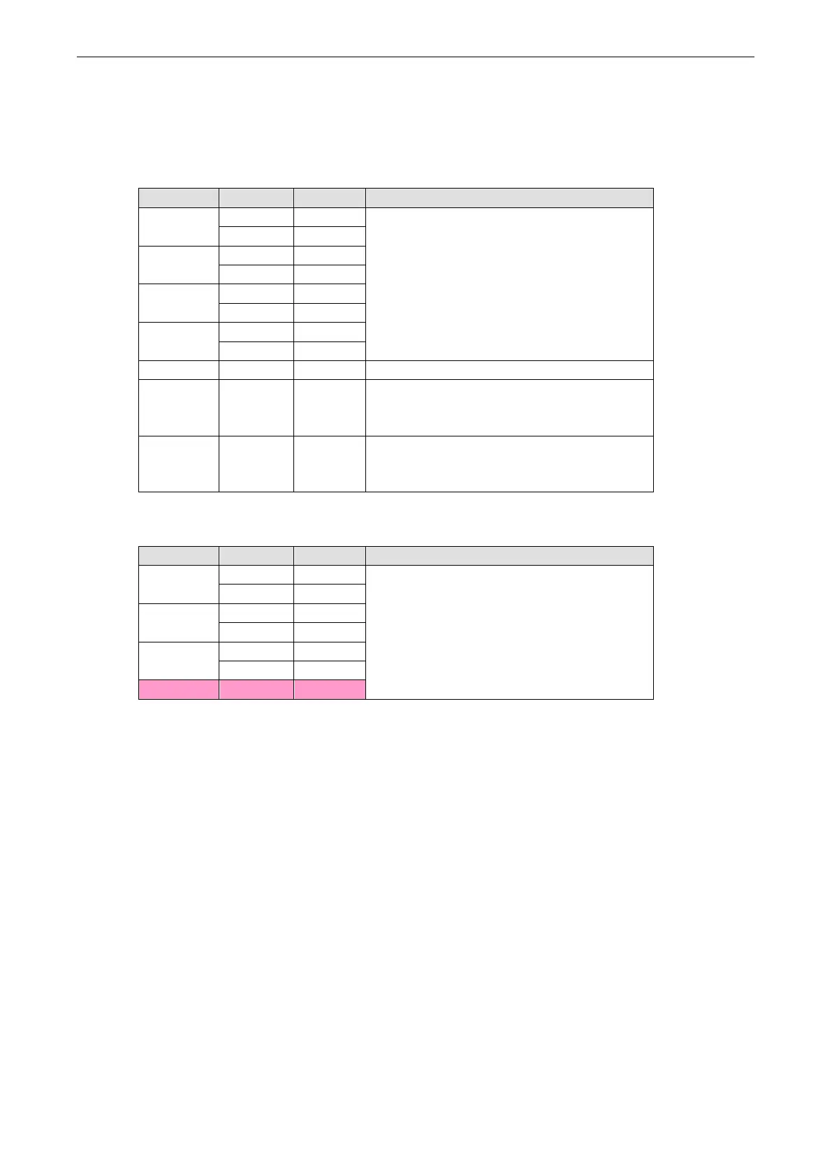
For Moxa boards that use MUE250, MUE450, and MUE850 chips, BAR2, which allocates 16 bytes, is the
vector base address that can be used to control serial interface and termination resistors according to the
following table.
Offset Bit Port # Parameters
0x4
0x0 : RS-232
0x1 : RS-422
0xF : RS-485 2W
0xB : RS-485 4W
[7..4] 2
0x5 [3..0] 3
0x6 [3..0] 5
[7..4] 6
0x7 [3..0] 7
0x8 [7..0] [8..1] GPIO – Input
0x9 [7..0] [8..1] GPIO direction configuration
0 : Set GPIO direction to input
1 : Set GPIO direction to output
0xA [7..0] [8..1] GPIO – Output (Termination Resistor)
0 : Low (0 Ohm)
1 : High (120 Ohm)
Especially, the interfaces of 4 ports model, such as CP-114EL and CP-114EL-I, are using the following offset
to set the interface of port 4.
Offset Bit Port # Parameters
0x4 [3..0] 1 0x0 : RS-232
0x1 : RS-422
0xF : RS-485 2W
0xB : RS-485 4W
[7..4] 2
0x5 [3..0] 3
[7..4] –
0x6
[7..4] –
0x7 [3..0] 4
For Baud Rate Setting
For General PC Com Port: CLK=1.8432MHz
Div = CLK/(Baud x 16)
But for Moxa Board: CLK=14.7456MHz
Div = CLK/(Baud x 16)
 Loading...