- 15 -
LED Indicators
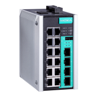
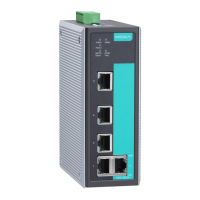
There are several LEDs on the EDS’s front panel. The function of each
LED is described in the following table.
PWR1 AMBER
On
Power is being supplied to power input
PWR1.
Off
Power is not being supplied to power
PWR2 AMBER
On
Power is being supplied to power input
Off
Power is not being supplied to power
input PWR2.
FAULT RED
On
1. The signal contact is open.
2. The port has been disabled
because the packets exceed the
ingress rate limit.
3. The loop connection in a single
switch is incorrect.
4. Invalid Ring port connection.
5. A failure during start-up.
Off
When a relay warning event is not
triggered.
MSTR/
HEAD
GREEN
On
1. The switch is set as the Master of
the Turbo Ring, or as the Head of
the Turbo Chain.
2. Hardware initialization failed
on and Fault blinking)
3. The switch is set as the Root of
Blinking
The EDS-405A/408A has become the
Ring Master of the Turbo Ring, or the
Head of the Turbo Chain, after the
Turbo Ring or the Turbo Chain is down.
Off
When the EDS-405A/408A is not the
Master of this Turbo Ring or is set as
the Member of the Turbo Chain.
CPLR/
TAIL
GREEN
On
When the EDS-405A/408A coupling
function is e nabled to form a back-up
path, or when it's set as the Tail of the
When the Turbo Chain is down.
Off
When the EDS-405A/408A
coupling function, or is set as the
Member of the Turbo Chain.
10M
(TP)
GREEN
TP port’s 10 Mbps link is active.
Data is being transmitted at 10 Mbps.
TP Port’s 10 Mbps link is inactive.
100M
(TP)
GREEN
TP port’s 100 Mbps link is active .
Data is being transmitted at 100 Mbps.
TP Port’s 100 Mbps link is inactive.
100M
(FX)
GREEN
FX port’s 100 Mbps is active.
Data is being transmitted at 100 Mbps.
FX port’s 100 Mbps is inactive.
 Loading...