- 9 -
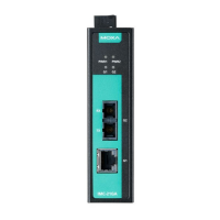
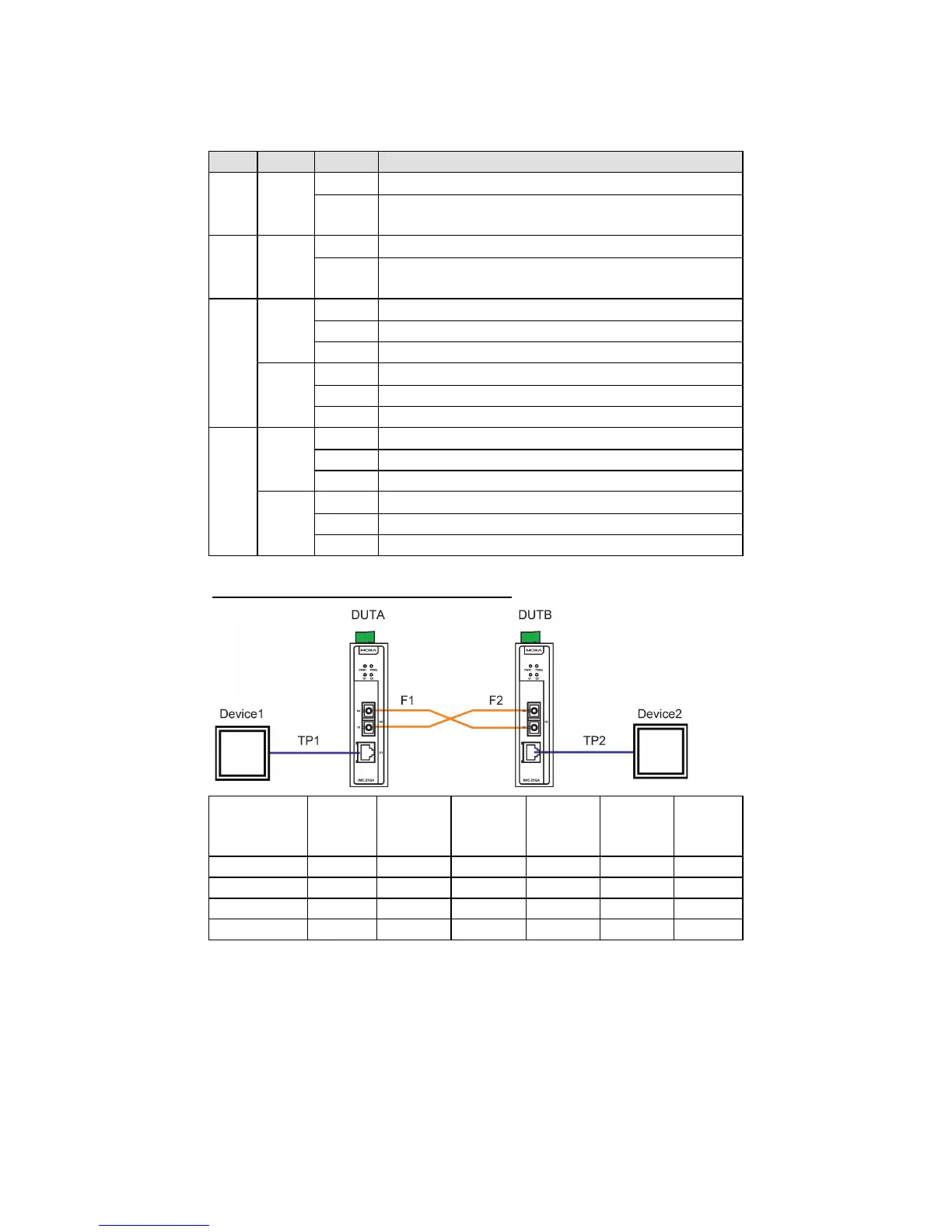
LED Indicators
The front panel of the Moxa IMC-21GA contains several LED indicators.
The function of each LED is described in the table below.
Power is being supplied to power input (V1+, V1-)
Off
Power is not being supplied to power input
Power is being supplied to power input (V2+, V2-)
Power is not being supplied to power input
(V2+, V2-)
TP port’s 1000 Mbps link is active
Data is being transmitted at 1000 Mbps
TP port’s 1000 Mbps link is inactive
TP port’s 10/100 Mbps link is active
Data is being transmitted at 10/100 Mbps
TP port’s 10/100 Mbps link is inactive
Fiber port’s 1000 Mbps link is active
Data is being transmitted at 1000 Mbps
Fiber port’s 1000 Mbps link is inactive
Fiber port’s 100 Mbps link is active
Data is being transmitted at 100 Mbps
Fiber port’s 100 Mbps link is inactive
LFP: DIP switch is set to “LFP” mode