3
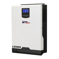
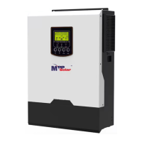
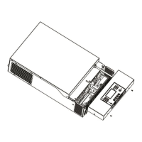
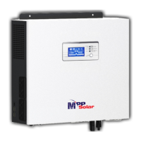
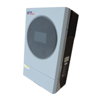
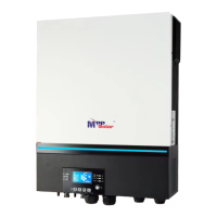
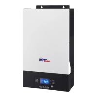
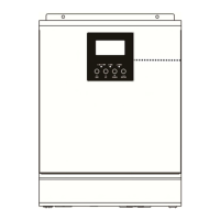
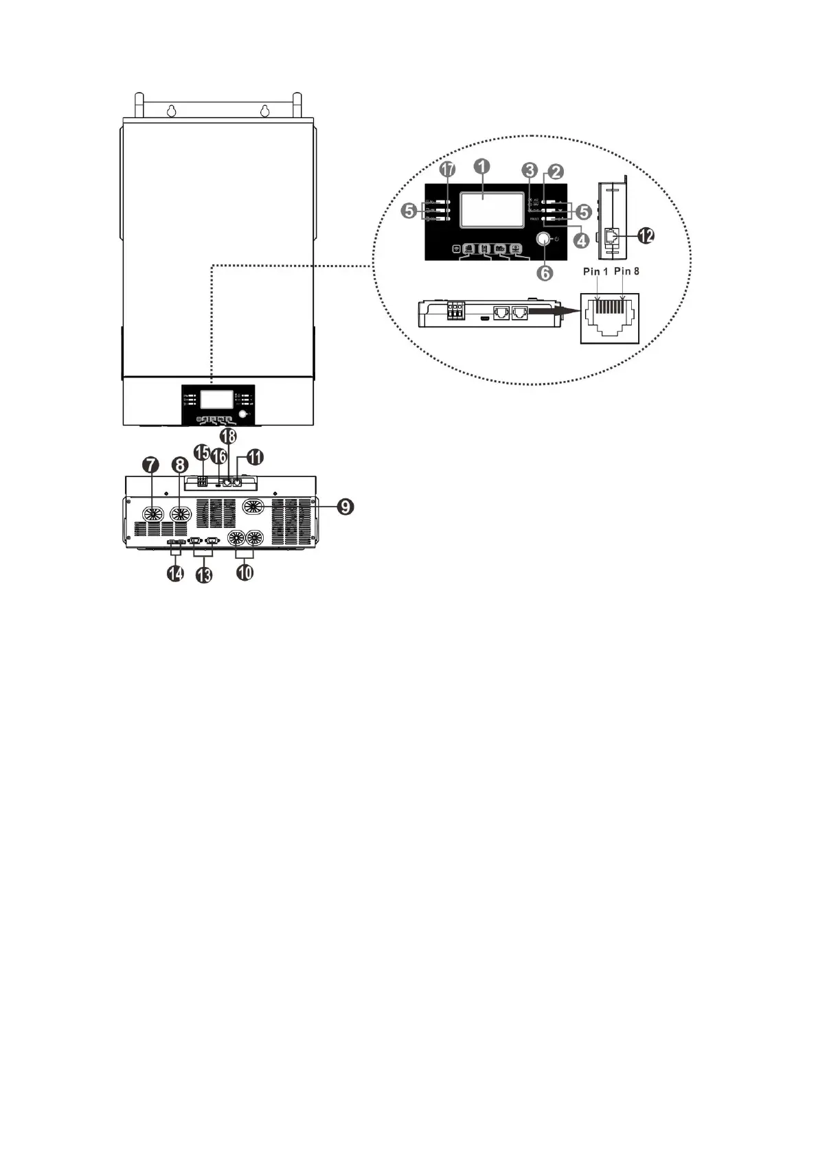
Product Overview
NOTE: For parallel model installation and operation, please check separate parallel installation guide for the
details.
1. LCD display
2. Status indicator
3. Charging indicator
4. Fault indicator
5. Function buttons
6. Power on/off switch
7. AC input connectors
8. AC output connectors (Load connection)
9. PV connectors
10. Battery connectors
11. RS-232 communication port
12. Remote LCD panel communication port
13. Parallel communication port (only for parallel model)
14. Current sharing port (only for parallel model)
15. Dry contact
16. USB communication port
17. LED indicators for USB function setting / Output source priority timer / Charger source priority setting
18. BMS communication port: CAN, RS-485 or RS-232
 Loading...