5 Installation and commissioning
71BA5831400-00 EN
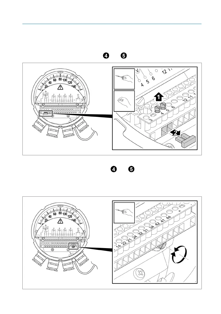
ü Open the cover plate.
1. Determine the necessary resistance value from the setting curve (8.6Ω in
this example).
2. Remove the bridge at terminals and .
Figure54: Bridge
3. Connect an ohmmeter to terminals and .
4. Set the required resistance value using the adjusting screw of the poten-
tiometer. Turning the adjusting screw to the right causes the resistance
value to increase, and turning it to the left causes it to decrease.
Figure55: Potentiometer adjusting screw