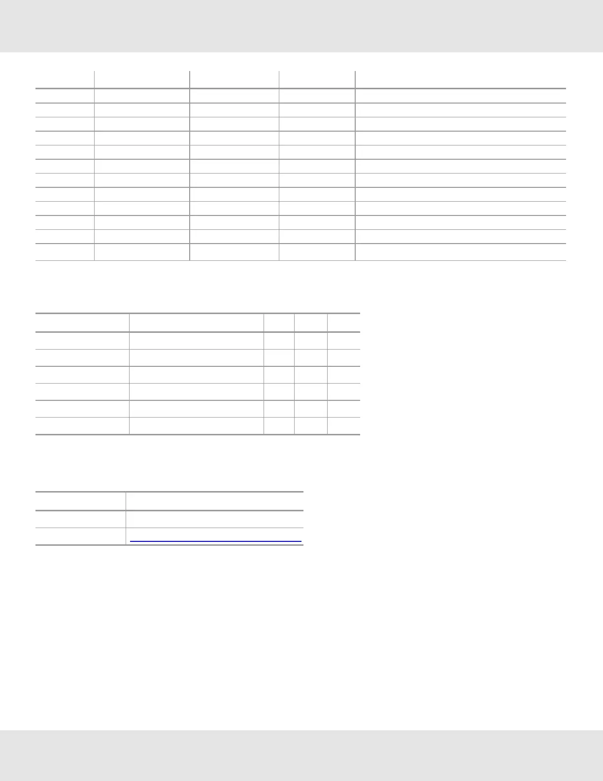
PIN # Function Direction DTE Label Comments
17 DIO5 Alternative I/O: SDI-MOSI
18 DIO8
19 Reserved
20 Reserved
21 RS-485 + (ISO) I/O Pass through Connection from Terminal Block
22 RS-485 - (ISO) I/O Pass through Connection from Terminal Block
23 RS-485 GND (ISO) GND Pass through Connection from Terminal Block
24 RS-232 TX OUT Reserved (Not used)
25 RS-232 TX INT Reserved (Not used)
26 RS-232 TX IN Reserved (Not used)
27 RS-232 TX OUT Reserved (Not used)
28 Spare I/O Reserved (Not used)
Serial Peripheral Interface (SPI) is supported with signals: SCK, CS, MISO and MOSI
3.1.2 ProtoCessor Pin Voltage Levels
Description Pin # Min Max Unit
Input High Voltage 4, 5 2 5.5 V
Input Low Voltage 4, 5 0 0.8 V
Input High Voltage All other inputs 2 3.6 V
Input Low Voltage All other inputs 0 0.8 V
Output High Voltage All Outputs except pins 12, 13 2.4 3.6 V
Output Low Voltage All Outputs except pins 12, 13 0 0.8 V
3.1.3 ProtoCessor Pin Headers
ProtoCessor recommends use of the following SAMTEC Pin Headers on host board:
Part Numbers TLW-1xx-x-S or MTLW-1xx-x-S
Manufacturer SAMTEC
Link to Data Sheets www.samtec.com/ftppub/pdf/tsw_th.pdf
9 ProtoCessor Design Guide