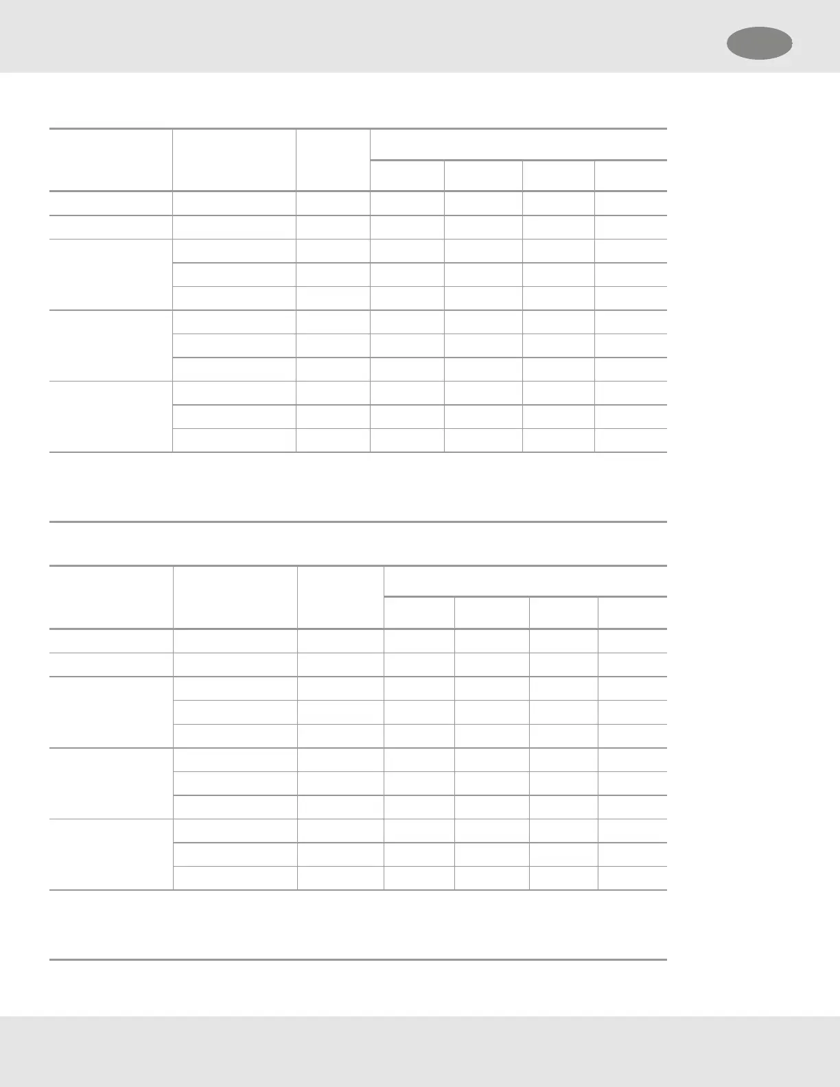
Table 1 Maximum Mounting Distance for Local Sensors, Imperial Units
Local Sensor 1 Local Sensor 2 Max.
Power
1
(W)
Max. Distance (ft)
18 AWG 16 AWG 14 AWG 12 AWG
Passive CB None 6.0 1280 2030 3230 5130
Passive MOS None 10.8 710 1130 1790 2850
Digital CB None 6.0 1280 2030 3220 5130
Digital CB 8.4 910 1450 2300 3660
Digital Toxic 6.7 1140 1810 2880 4580
Digital Toxic None 3.6 2130 3380 5370 8550
Digital Toxic 4.3 1770 2820 4480 7120
Digital CB 6.7 1140 1810 2880 4580
IR Sensor None 8.9 860 1370 2180 3470
Digital CB 11.8 650 1040 1650 2620
Digital Toxic 9.6 800 1270 2020 3210
1
- When sizing a system's 24V supply, a 1A inrush current with a 1ms duration should be considered
for each device on the power supply
Assumes transmitter was ordered with relays
Table 2 Maximum Mounting Distance for Local Sensors, Metric Units
Local Sensor 1 Local Sensor 2 Max.
Power
1
(W)
Max. Distance (m)
1 mm
2
1.5 mm
2
2.5 mm
2
4 mm
2
Passive CB None 6.0 470 710 1180 1890
Passive MOS None 10.8 260 390 660 1050
Digital CB None 6.0 470 710 1180 1890
Digital CB 8.4 340 510 840 1350
Digital Toxic 6.7 420 630 1050 1690
Digital Toxic None 3.6 790 1180 1970 3150
Digital Toxic 4.3 650 980 1640 2620
Digital CB 6.7 420 630 1050 1690
IR Sensor None 8.9 320 480 800 1280
Digital CB 11.8 240 360 600 960
Digital Toxic 9.6 290 440 740 1180
1
- When sizing a system's 24V supply, a 1A inrush current with a 1ms duration should be considered
for each device on the power supply
Assumes transmitter was ordered with relays
26
3 Installation US