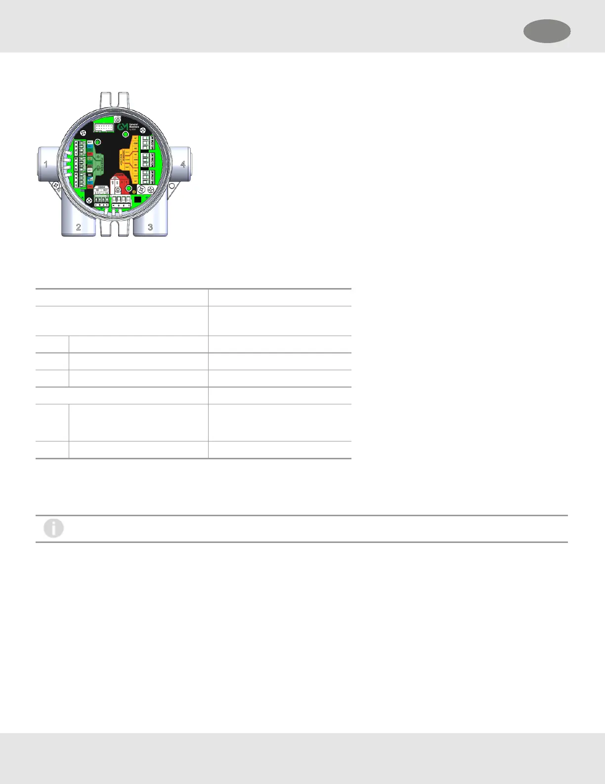
Figure 28 PC Board with Relays
Relay Specifications
Table 8 Relay Specifications
Temperature Range -40 to +85°C (-40 to 185°F)
Relays SPDT (Single Pole Double
Throw)
Fault Normally Energized
Warning Configurable
Alarm Configurable
Relay Rating
125 or 250 VAC (Resistive) 5A, 100K Cycles
1.6 HP @ 250VAC
30 VDC (Resistive) 5A, 100K cycles
If using ACpower, the relay wires should not be run within the same conduit or cable tray as the DCpower supplied to the
S5000 or the S5000 junction box. A separate wire entry on the device should be used for ACpower connected to the relays.
The S5000 is built with an additional wire entry to allow this.
Exceeding the volt-amp rating of the relay can cause damage to the switching contacts.
Relay Connections to Inductive Loads
If connecting the relays to motors, fluorescent lighting, or other inductive loads, it is necessary to suppress any sparks or
inductive feedback that may occur at the relay contact. These effects may render the unit inoperative.
One way to reduce these effects is to install a Quencharc
®
(P/N630413) across the load being switched.
Fault Relay Wiring and Configurations
The Fault relay state in non-fault operating condition is Energized and terminal connections are supplied for Normally Closed
and Normally Open.
The energized fault relay setting provides an electrical path for fail-safe relay operation. In the event of any failure, including
loss of power, the relay will change to the de-energized state to indicate a fault condition.
32
3 Installation US