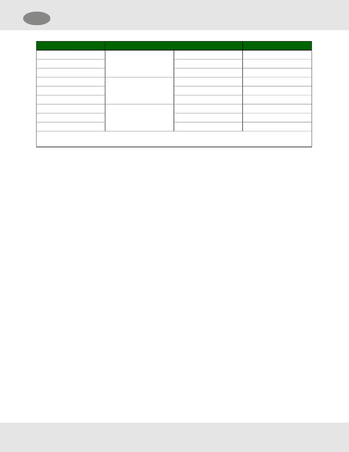
P4* PCB Label Function
1
WARNING
N/C Low Alarm Relay NC
2 COM Low Alarm Relay COM
3 N/O Low Alarm Relay NO
4
ALARM
N/C High Alarm Relay NC
5 COM High Alarm Relay COM
6 N/O High Alarm Relay NO
7
TRBL**
N/C Trouble Alarm Relay NC
8 COM Trouble Alarm Relay COM
9 N/O Trouble Alarm Relay NO
* P4 Connections are installed only when the optional Relays are included
** Trouble relay is a fail-safe so it is energized for normal operation, functions are labeled for normal operation.
NOTE:The starting delay period normally takes approximately 3 minutes but under some circumstances can
take longer. For optimum performance, it is recommended that a calibration be performed after 24 hours of
operation.
SMC 5100-XX-IT Toxic Gas Detector Module 17
US 4 Installation

 Loading...