STARTER AND CHARGING SYSTEMS
46
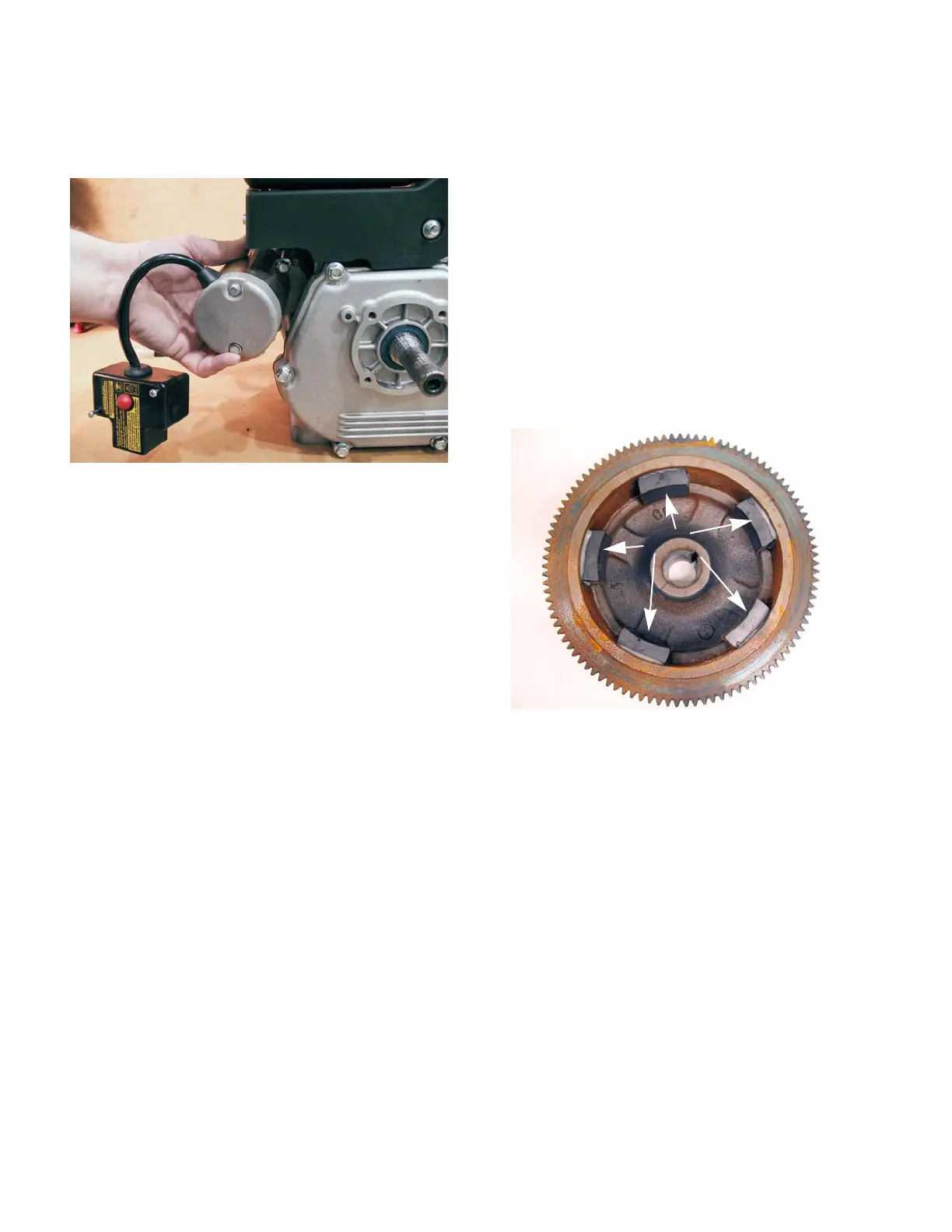
4. Pull back on the starter approximately 1/2”. Then
angle it away from the engine while sliding it out
of the engine.
See Figure 6.13.
NOTE: Before condemning a starter make sure
to bench test it. To bench test a starter:
A. Remove the starter from the engine.
B. Plug the extension cord into the switch
housing.
C. Hold the starter down and press the starter
button.
• If the starter works on the bench, confirm that
the engine crankshaft rotates with normal force.
• If the crankshaft does not rotate with normal
force, identify and repair the engine problem.
NOTE: This includes adjusting the valve lash.
• If the crankshaft rotates with normal force but the
starter is unable to turn it, replace the starter.
• If the starter does not work, replace the starter.
4. Install the starter by following the above steps in
reverse order.
NOTE: Tighten the starter screws to a torque of
195 - 221 in-lbs (22-25 Nm).
Charging system
Description
Some engines are equipped with a charging system.
The charging system consists of:
• Alternator stator: The stator consists of copper
field windings around an iron core. The stator is
attached to the engine block beneath the fly-
wheel.
• Alternator rotor: The rotor consists of five mag-
nets on the inside of the flywheel that rotate
around a stator that is mounted to the cylinder
block. As the crankshaft and flywheel rotate, the
moving magnets induce a charge in the stator.
See Figure 6.14.
• A rectifier: A set of diodes that turn the AC cur-
rent into DC current.
Figure 6.13
Pull back and angle the
starter away while
sliding it out
Figure 6.14
Magnets
 Loading...


