Variable Speed Drive
16). Secure the right hand ball joint to the right hand
axle assembly with the lock washer and nut
removed earlier, using a 1/2" wrench and a 9/16
socket.
17). Secure the right hand ball joint jam nut to the
right hand drag link using a 1/2" wrench and an
11/16 wrench.
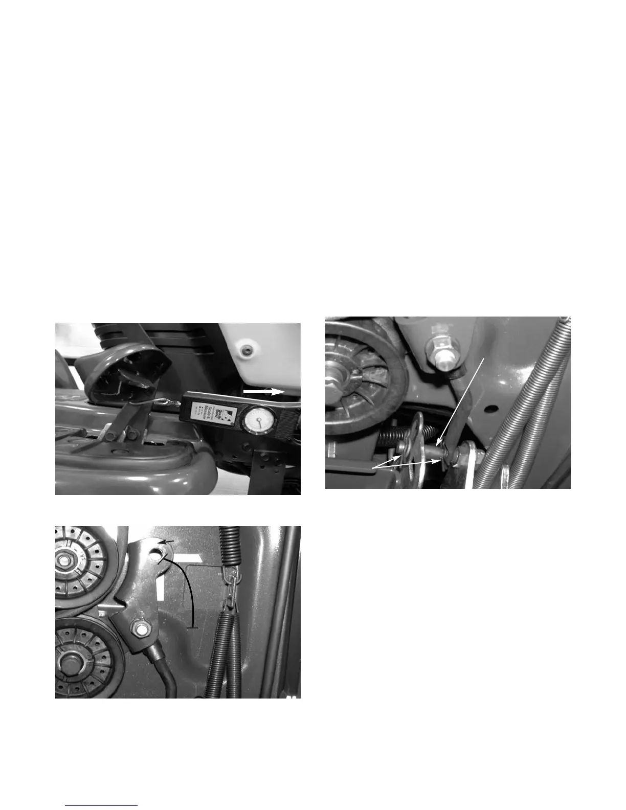
FIGURE 1.
IMPORTANT: The AutoDrive pedal is properly
adjusted when the hole found in the double-idler
bracket has approximately 1-3/8" of travel with
ten pounds of pressure applied to the AutoDrive
pedal. See figures 1 and 2.
Autodrive Pedal Adjustment
1). Locate the speed control assembly on the
underside of the steering support bracket.
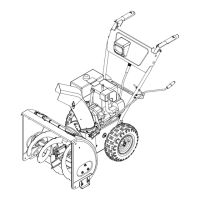
2). Remove both hairpin clips from the main pin on
the speed control assembly. See figure 3.
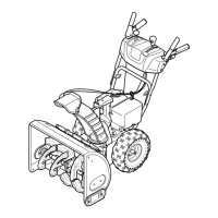
10 Lbs.
Double Idler
Bracket
1-3/8"
FIGURE 2.
FIGURE 3.
NOTE: Be careful not to lose the small flat
washers found on the main pin.
NOTE: Make certain both hairpins are put back
in from the top of the main pin during reassem-
bly.
3). Remove the AutoDrive pedal return spring.
4). Using two 9/16" wrenches, remove the main pin
from the speed control assembly.
5). Thread the idler adjustment rod inward or out-
ward until the proper adjustment has been
achieved.
REASSEMBLE THE AUTODRIVE PEDAL IN THE
REVERSE ORDER ABOVE.
Main Pin
Hairpin
Clips
2
18). Install the left hand ball joint using steps 15, 16,
and 17.
NOTE: Make certain the same amount of rota-
tions are used on the left ball joint as the right
ball joint.