Chapter 7: Ignition System
68
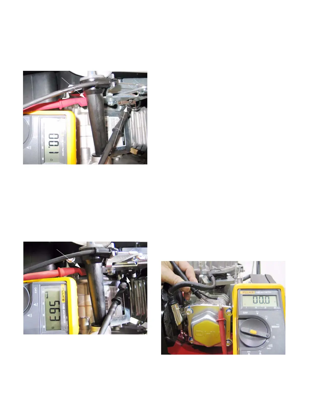
3b. Connect an Ohm meter between the termi-
nal and a ground point. The reading should
approach zero when the bail is released or
the switch is turned off, closing the con-
tacts. See Figure 7.3.
NOTE: If the reading is high, the contacts may
be burnt or there is a bad ground to the switch.
This could prevent the engine from shutting
down rapidly.
3c. The reading should be high when the bail is
pulled down or the switch is in the run posi-
tion, reflecting the resistance in the primary
windings of the ignition module.
See Figure 7.4.
NOTE: If the reading is low, the module is
shorted to ground and may not produce a spark.
The wire will need to be traced back to the mod-
ule to find the short.
3d. Alternatively, a jumper wire could be con-
nected to the same locations. Use a com-
mercially available spark checker to see if
the ignition is working or not.
• If the jumper disables the ignition, but releasing
the bail does not, the problem lies in the switch.
• If the jumper does not disable the ignition, then
the wire that connects the switch to the ignition
module may have a fault, or the ignition module
itself may be faulty. Further investigation is
required.
• If the problem is a lack of spark when the bail is
pressed against the upper handlebar, disconnect
the wire from the switch using a 7mm wrench.
Isolate the wire from incidental contact with
ground, and test the ignition. If it fails to spark,
the wire may be shorted or the ignition may be at
fault. Further investigation is required.
3e. If further investigation is required, remove
the recoil assembly by following the steps
described in Chapter 6: Starter.
3f. Visually trace the wire from the stop switch
to the connector on the module, and inspect
the wire for any damaged insulation or
potential contact with ground.
3g. Unplug the wire from the spade terminal on
the module or unplug the insulated bullet
connectors, depending on the production
date of the engine, and check continuity to
ground from the female terminal on the wire
from the switch. Resistance (Ohms) should
be zero with the bail released or the switch
turned off. See Figure 7.5.
Figure 7.3
Ground connection
Stop
switch
connection
Safety bail in
OFF position
Figure 7.4
Ground connection
Stop switch
connection
Safety bail
in RUN
position
Figure 7.5
Safety bail in OFF
position, Module
primary windings
are grounded
www.mymowerparts.com
For Discount White Outdoor Parts Call 606-678-9623 or 606-561-4983
 Loading...


