Chapter 10: Crankshaft, piston and Connecting Rod
87
There are a a few different paths that can be followed
when disassembling an engine. This chapter will cover
the removal of components in one order, but it is written
so that the technician can jump around to the compo-
nent being removed.
The first step to disassemble the engine is to remove
the engine from the application by following the steps
described in the service manual for that particular
application.
NOTE: The MTD engine is NOT to be opened
under warranty. If an internal engine failure
occurs during the warranty period, replace the
whole engine, no short blocks.
1. Drain and save the oil from the engine by follow-
ing the steps described in Chapter 1: Introduc-
tion.
2. Remove the fuel tank by following the steps
described in Chapter 4: Fuel system and Gover-
nor.
3. Remove the starter by following the steps
described in Chapter 6: Starter systems.
4. Remove the flywheel and ignition module by fol-
lowing the steps described in Chapter 7: Ignition
system.
5. Remove the muffler by following the steps
described in Chapter 8: Exhaust.
NOTE: At this point it would be a good idea to
service the PCV valve by following the steps
described in Chapter 5: Lubrication.
6. Remove the cylinder head by following the steps
described in Chapter 9: Cylinder head.
7. Clean the cylinder bore and remove all carbon.
8. Turn the engine over.
9. Remove the sump bolts using a 10mm wrench
on the 1P61/65 and a 12mm wrench on the
1P70.
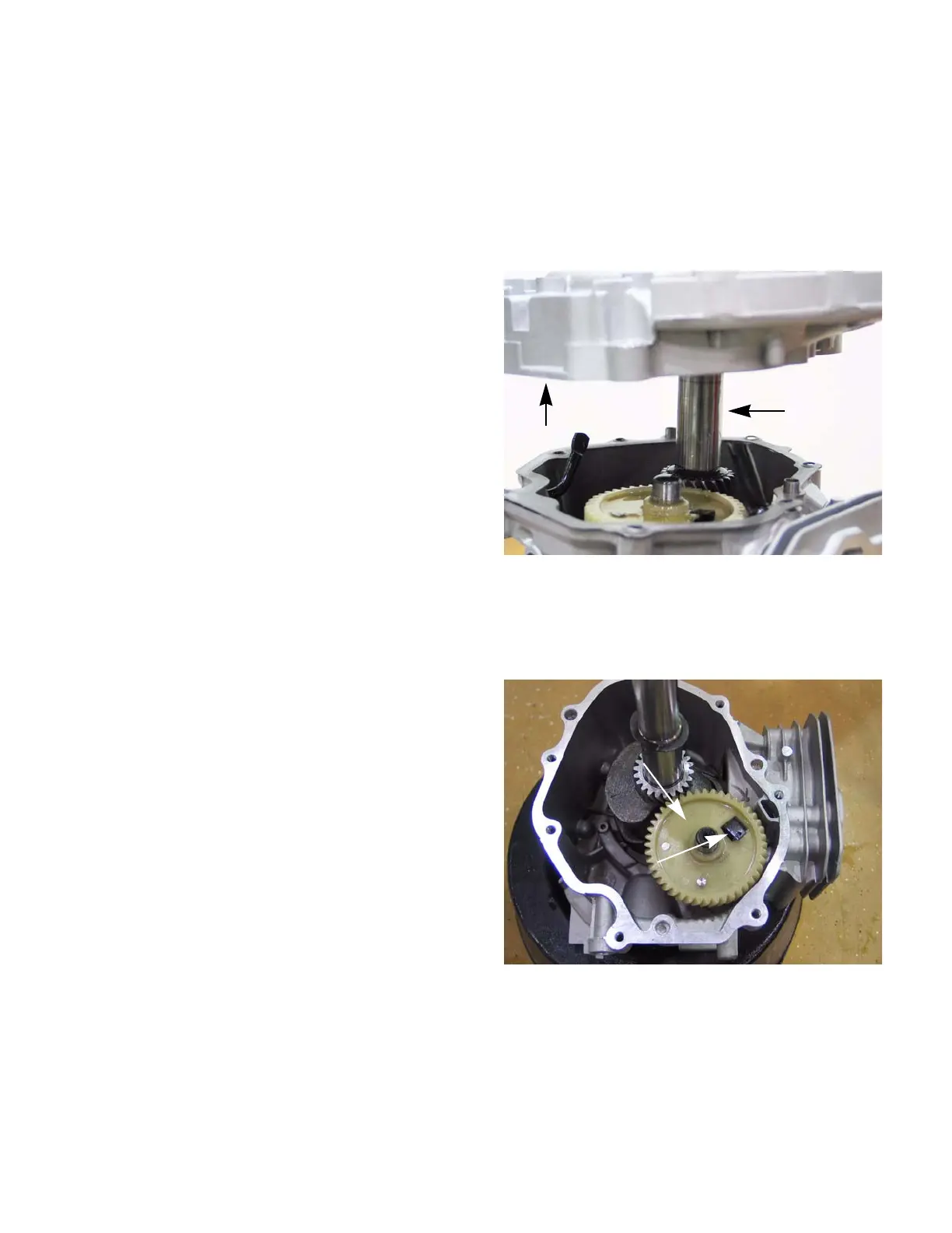
10. Carefully slide the sump off of the crank shaft.
See Figure 10.1.
NOTE: The thrust washer should be removed
when the sump is removed.
11. Remove the camshaft. See Figure 10.2.
NOTE: Align the timing marks to allow easier
removal of the cam shaft and to help protect the
compression relief from damage.
Figure 10.1
Sump
Crank shaft
Cam shaft
Compression
relief
Figure 10.2
CHAPTER 10: CRANKSHAFT, PISTON AND CONNECTING ROD
www.mymowerparts.com
For Discount White Outdoor Parts Call 606-678-9623 or 606-561-4983
 Loading...


