Chapter 9: Cylinder Head
86
NOTE: Only the intake valve has a valve guide
seal. See Figure 9.9.
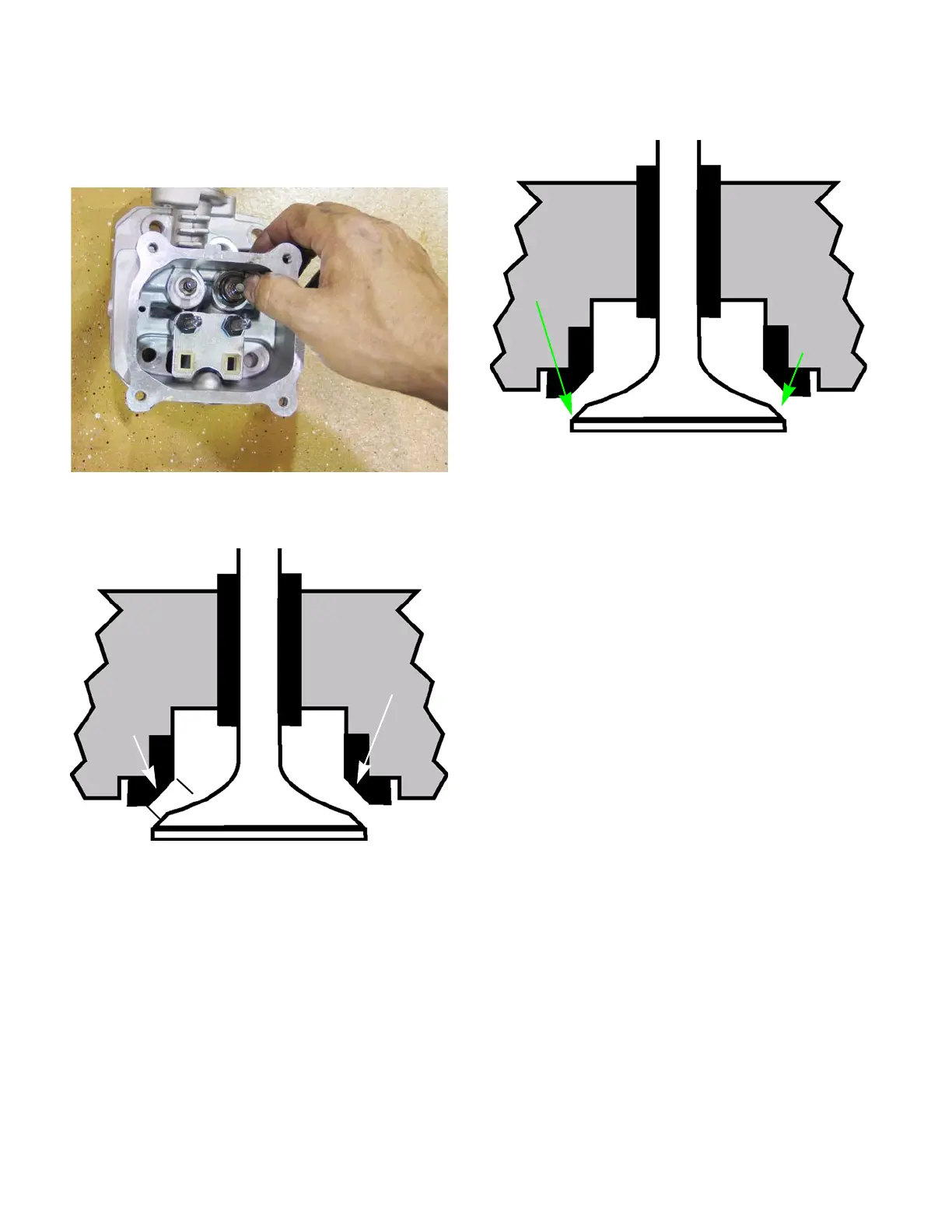
6. Inspect the valve seat. See Figure 9.10.
• Valve seats are 45 degrees, with a 15 degree
topping cut and a 75 degree narrowing cut.
• Seat width should be .043”-.050” (1.1-1.3mm)
with a margin of .024” (.6mm) on the exhaust
valve and .027” (.7mm) on the intake valve.
NOTE: The valve seat can be ground to clean it
up as long as the finished seat is within the toler-
ances listed above.
7. Inspect the valve stem. See Figure 9.11.
8. Inspect the valve springs.
NOTE: Valve spring free length should be at
least 1.22” (28.5mm). Original length is 1.44”
(36.6mm).
9. Install the valves in the cylinder head by follow-
ing steps 2 - 5 in reverse order.
10. Test the valves for leaks by:
10a. Place the cylinder head on a couple of
wood blocks with the valves facing up.
10b. Pour a small amount of gasoline or parts
cleaning solvent into the combustion
chamber (just enough to cover the
valves).
10c. Let the cylinder head sit for ten minutes.
10d. Check for gasoline leaking out of the intake
and exhaust ports.
11. Install the cylinder head by following the steps
described earlier in this chapter.
12. Set the valve lash by following the steps
described in Chapter 1: Introduction.
Figure 9.9
Figure 9.10
Seat angle is 45
o
.043-.050”
Figure 9.11
45
o
Inspect for a
burnt edge
www.mymowerparts.com
For Discount White Outdoor Parts Call 606-678-9623 or 606-561-4983
 Loading...


