Chapter 7: Ignition System
76
5. Position the brake assembly so that the edge of
the brake pad that is nearest the slotted hole is
roughly .050” (1.27mm) from the flywheel, then
tighten the screws. See Figure 7.21.
NOTE: The shank of an unused drill bit may be
used as a feeler gauge
6. Tighten the two bolts that hold the brake assem-
bly in place.
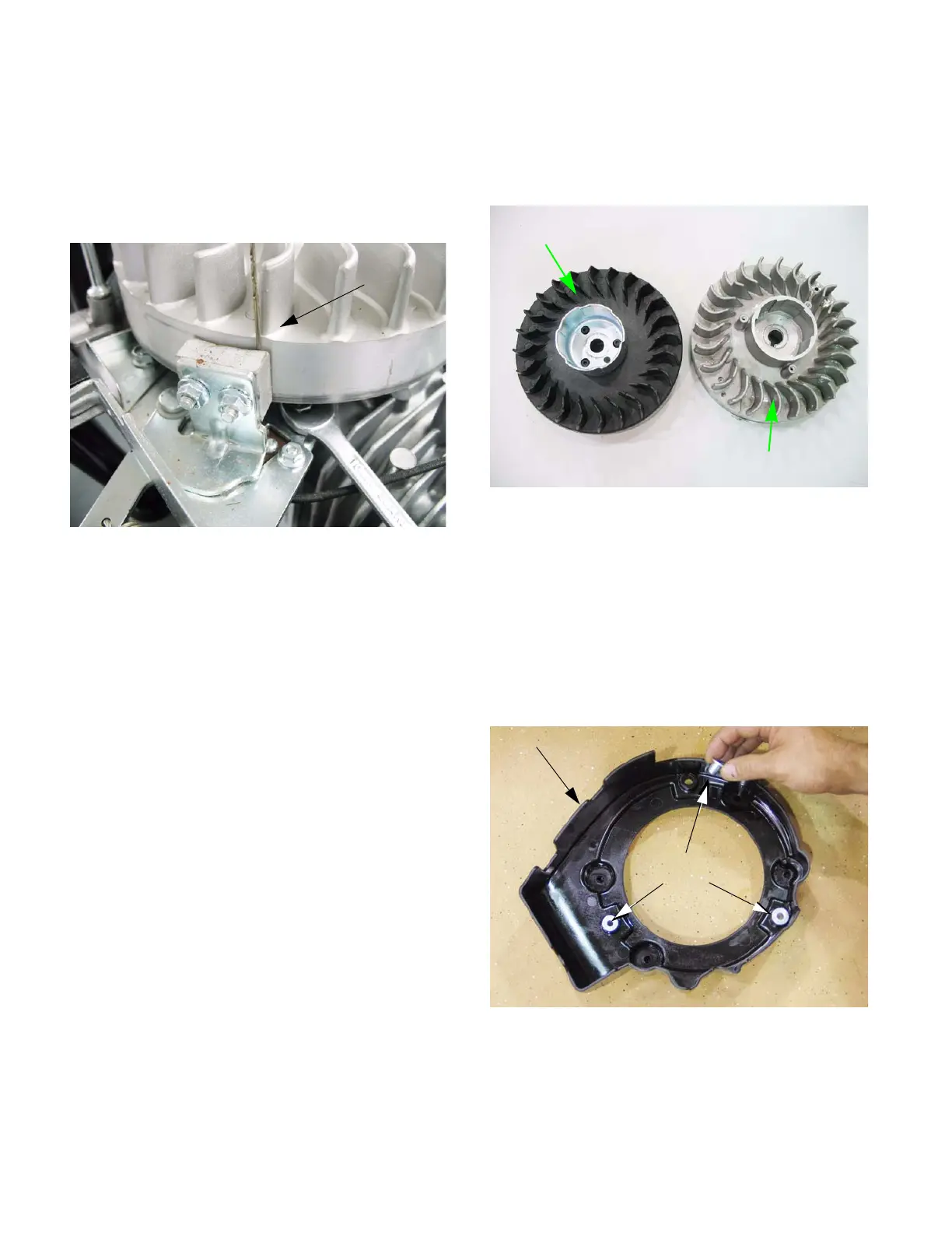
Flywheel
There are two types of flywheels available for the MTD
engine. An aluminum flywheel and a 3-piece cast iron
flywheel. See Figure 7.22.
NOTE: The procedure for removing the flywheel
is the same for both aluminum and cast iron fly-
wheels.
To remove the flywheel:
1. Remove the recoil assembly by following the
steps described in Chapter 6: Starter.
2. Lift the fan shroud off of the three studs that
locate it. See Figure 7.23.
Figure 7.21
Drill bit used
for gauge
Figure 7.22
Cast iron flywheel
Aluminum flywheel
Figure 7.23
Fan shroud
Shoulder
bushings
Shoulder
bushings fit
over studs
www.mymowerparts.com
For Discount White Outdoor Parts Call 606-678-9623 or 606-561-4983
 Loading...


