16
INM5000-6 Jul 2010
6.7.3 Testing
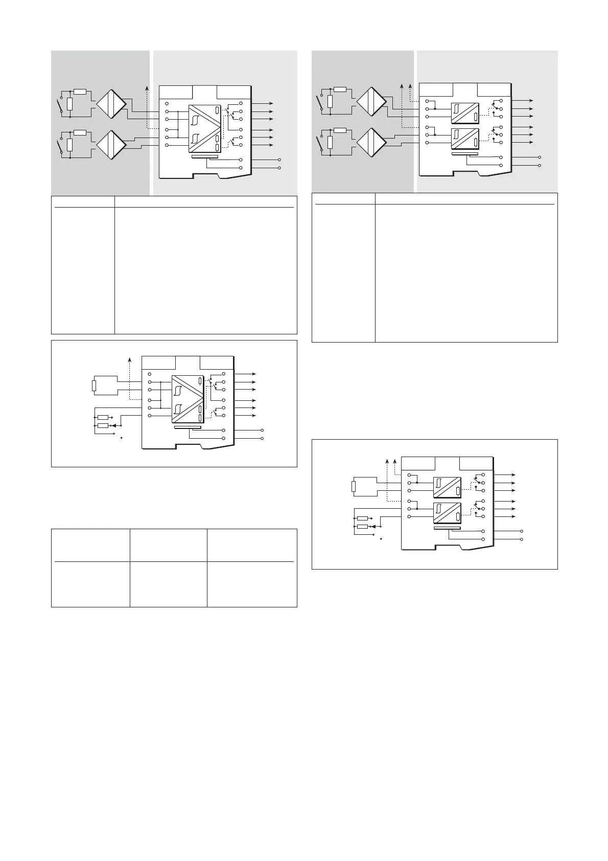
Make the safe- and hazardous-area connections shown in figure 6.15
and check the status of the output contacts for each channel in turn (with
a 22kΩ resistor connected to the other channel) as shown in table 6.6.
Table 6.6
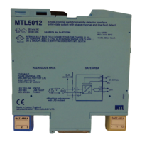
6.8 MTL5018 single-pole, changeover
relay, two-channel, switch/proximity
detector with line fault detection and
phase reversal
The MTL5018 modules enable each of two safe-area loads to be relay-
controlled by switches or proximity detectors in a hazardous area. Line
fault detection (LFD) and output phase reversal (see 3.1.3) facilities are
included.
6.8.1 Wiring connections
See figure 6.16 for wiring connections.
Note: Reactive loads must be adequately suppressed.
6.8.2 Line fault detection
(See section 3.1.4 for definition of a line fault)
On each channel, input line faults (open- or short-circuit) are indicated
by an LED and the de-energising of the output.
LFD is enabled/disabled by switches located on the top of the module.
Note that if the LFD facility is enabled for switch inputs, the resistors
shown in figures 6.16 and 6.17 MUST be fitted.
6.8.3 Testing
Make the safe- and hazardous-area connections shown in figure 6.17
and check the status of the output contacts for each channel in turn (with
a 22kΩ resistor connected to the other channel) as shown in table 6.7.
6.9 MTL5018AC single-pole, changeover
relay, two-channel, switch/proximity
detector with line fault detection and
phase reversal
The MTL5018AC modules enable each of two safe-area loads to be
relay-controlled by switches or proximity detectors in a hazardous area.
Line fault detection (LFD) and output phase reversal facilities are included
(see section 3.1.3 ).
6.9.1 Wiring connections
See figure 6.18 for wiring connections.
Note: Reactive loads must be adequately suppressed.
6.9.2 Line fault detection
(See section 3.1.4 for definition of a line fault)
On each channel, input line faults (open- or short-circuit) are indicated
by an LED and the de-energising of the output. LFD is enabled/disabled
by switches located on the top of the module.
Note that if the LFD facility is enabled for switch inputs, the resistors
shown in figures 6.18 and 6.19 MUST be fitted.
Terminal Function
1 Input –ve (Ch 1)
2 Input +ve (Ch 1)
3 Earth leakage detection
4 Input –ve (Ch 2)
5 Input +ve (Ch 2)
7 Line fault detection
8 Output (Ch 2)
9 Output (Ch 2)
10 Line fault detection
11 Output (Ch 1)
12 Output (Ch 1)
13 Supply –ve
14 Supply +ve
Artisan Technology Group - Quality Instrumentation ... Guaranteed | (888) 88-SOURCE | www.artisantg.com