INM5000-6 Jul 2010
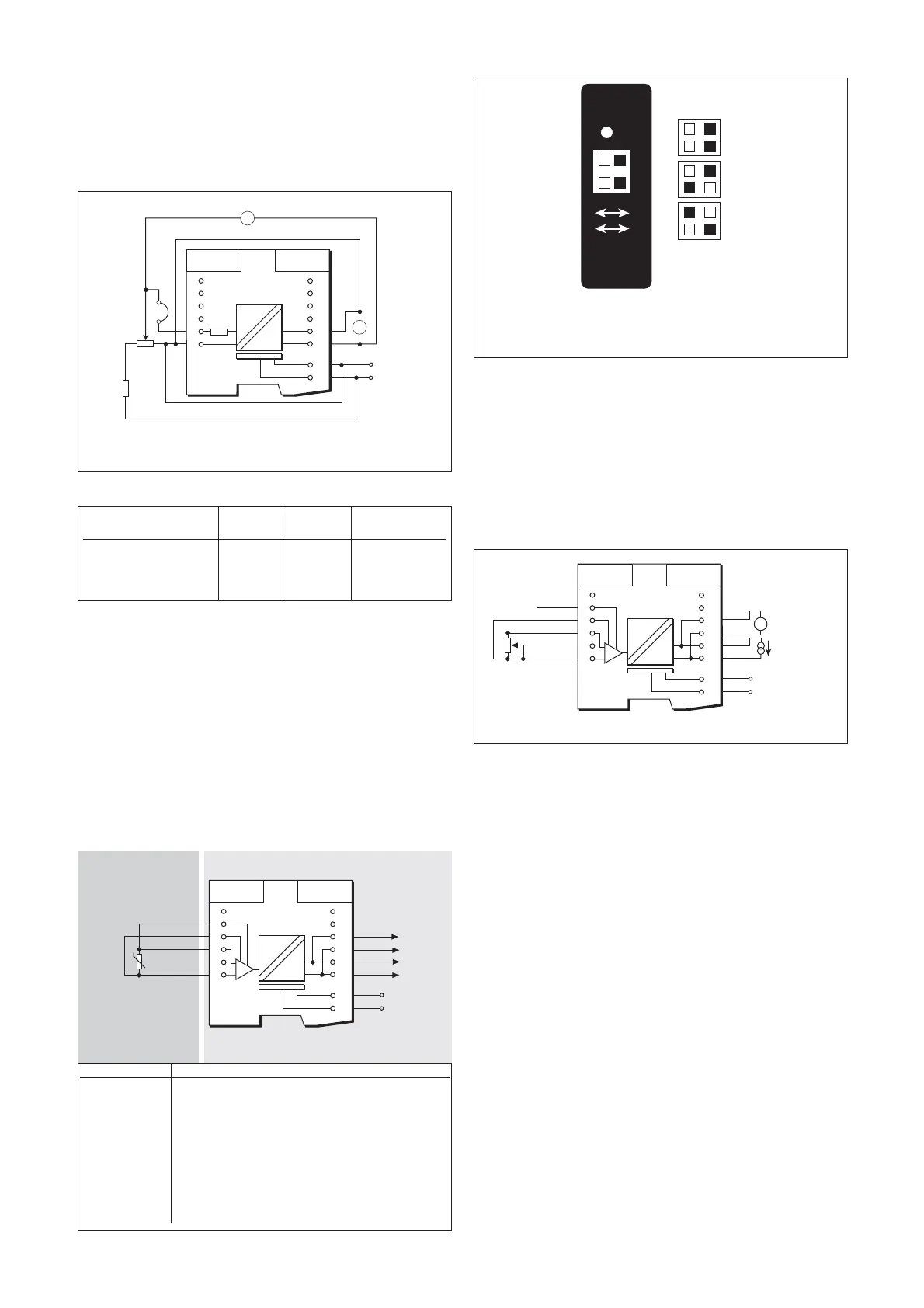
6.29.1 Input mode selection
The unit is factory set for 3-wire RTD mode. To select 2-wire or 4-wire RTD
modes, configure the switches located on the top of the unit in
accordance with the diagrams in figure 6.68.
6.29.2 Wiring connections
Warning: Check polarity of terminals used for safe-area connections.
Safe-area terminals 9, 10, 11 and 12 are unipolar so it is essential to
select a positive terminal on the MTL5082 for connection to the positive
of the RTD input card.
See figure 6.67 for wiring connections.
6.29.3 Testing
Make the safe- and hazardous-side connections shown in figure 6.69,
ensuring that the configuration switches on top of the unit are set to 3-
wire RTD input mode (see figure 6.68). Carry out the following tests and
checks using a resistance box, with a range of 0 to 400Ω, and a
voltmeter, covering the range 47.0mV to 2.100V.
1. Set the resistance box to any value in the range 10Ω to 400Ω,
switch on the power supply and check that the green power
(PWR) LED comes on and remains steady. If the LED is flashing
after 5 seconds, either the test-wiring set-up is faulty or the unit is
faulty.
2. Check that the output voltage changes as the input resistance is
varied within the range 10Ω to 400Ω.
3. Short circuit the input and check that the output voltage is
≤51.6mV after 5 seconds.
4. Open circuit the input and check that the output voltage is
≤2.071V after 5 seconds and that the green PWR LED is flashing.
5. Set the input resistance to 200Ω and check that the output
voltage settles to 1.0V ±32mV.
6.30 MTL5099 dummy isolator
The MTL5099 is used with other MTL5000 Series units to provide
termination and earthing facilities for unused cable cores from
hazardous areas.
6.30.1 Wiring connections
See figure 6.70 for wiring connections.
6.28.3 Testing
Make the safe and hazardous-area connections shown in figure 6.66
Note: A millivoltmeter capable of measuring to within 1µV should be
used for V1.
Carry out the checks shown in table 6.13, using RV1 to vary the output
at V2 for the first test.
Table 6.13
6.29 MTL5082 resistance isolator
The MTL5082 connects to a 2-, 3- or 4-wire resistance temperature
device (RTD) or other resistance located in a hazardous area, isolates it
and repeats the resistance to a monitoring system in the safe area. The
module drives upscale in the case of open circuit detection. The number
of wires which can be connected on the safe-area side of the unit is
independent of the number of wires connected on the hazardous-area
side.
The module is intended typically, but not exclusively, for use with Pt100 3-
wire RTDs. Switches located on top of the module allow selection of 2-, 3-
or 4-wire connection. The MTL5082 is also used as an alternative, non-
configurable MTL5074, for use in RTD applications where a resistance
input is preferred or needed instead of 4 to 20mA.
Artisan Technology Group - Quality Instrumentation ... Guaranteed | (888) 88-SOURCE | www.artisantg.com