6.11 MTL5022 loop-powered
solenoid/alarm driver, IIB
The MTL5022 enables a device located in the hazardous area to be
controlled by a switch located in the safe area. Suitable for IIA and IIB
applications.
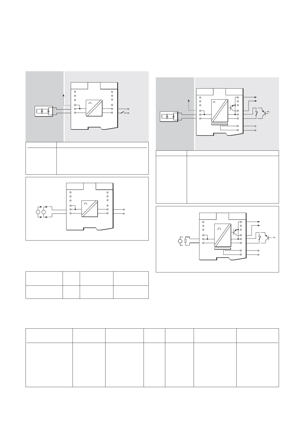
6.11.1 Wiring connections
See figure 6.22 for wiring connections.
6.11.2 Testing
Make the safe- and hazardous-area connections shown in figure 6.23,
apply 24V to terminals 11 and 12 and, with no load, check voltage and
short-circuit current levels at terminals 1 and 2 as follows
18
INM5000-6 Jul 2010
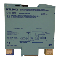
6.12 MTL5023 solenoid/alarm driver with
line fault detection and phase reversal
The MTL5023 enables a device located in the hazardous area to be
controlled by a volt-free contact or logic signal located in the safe area.
Line fault detection (LFD) and output phase reversal (see 3.1.3) facilities
are included.
6.12.1 Wiring connections
See figure 6.24 for wiring connections.
6.12.2 Line fault detection
(See section 3.1.4 for definition of a line fault)
Hazardous-area line faults are signalled to the safe area by an LED and
a solid-state switch which de-energises when a line is open- or short-
circuited.
6.12.3 Testing
Make the safe- and hazardous-area connections shown in figure 6.25
and carry out the voltage and current checks as shown in table 6.8.
Input Status Output Short-circuit
voltage LED voltage current
(terminals 11 & 12) yellow (terminals 1 & 2) (terminals 1 & 2)
24V dc On 22 to 24V –
24V dc On – 61 to 70mA
Terminal Function
1 Output –ve
2 Output +ve
3 Earth leakage detection
11 Supply –ve
12 Supply +ve
Hazardous area Safe area
Figure 6.22: MTL5022 wiring diagrm and connections
Input switch LFD Status Output Output
SW1 Phase reverse LED LED voltage current
(terminals 11 & 12) Load switch (red) (yellow) (terminals 1 & 2) (terminals 1 & 2)
Closed 2kΩ Normal Off On >19.5V –
Open 2kΩ Normal Off Off <4.5V –
Closed 15kΩ Normal On On >21.0V –
Open 15kΩ Normal On Off <7.0V –
Closed Short-circuit Normal On On – >45mA
Open Short-circuit Normal On Off – <6mA
Closed Short-circuit Reverse On Off – <6mA
Table 6.8
Artisan Technology Group - Quality Instrumentation ... Guaranteed | (888) 88-SOURCE | www.artisantg.com