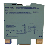
6.24 MTL5051 serial data comms isolator
The MTL5051provides either bi-directional serial data communications
from a computer system in a safe area to instrumentation in a hazardous
area or data communications across a hazardous area. It is used to
provide a fully floating dc supply for, and serial data communications to
MTL640 text displays and MTL650 series text and graphics terminals or
to other IS and non-IS instrumentation and keyboards.
6.24 .1 Wiring connections
See figures 6.52 and 6.53 and the terminal specifications in tables 6.11
and 6.12 for wiring connections. See also section 6.22.2 on hazardous-
area interfacing.
6.24.2 Hazardous-area interfacing
Displays/terminals: For details of interfacing with MTL640 and
MTL650 series displays/terminals (as an alternative to the MTL696
communications interface) see the appropriate product instruction
manual.
24
INM5000-6 Jul 2010
from either. For smart two–wire transmitters it provides bi-directional
communication signals superimposed on the 4/20mA signal. The
MTL5048 can also be used for isolating and passing a 4/20mA
signal from the safe area to the hazardous-area. The transmitter can
be interrogated either from the operator station or by a hand-held
communicator (HHC) for both the channels.The MTL5049 isolates and
passes on two 4 to 20mA signals from a controller located in a safe area
to two loads in a hazardous area.
6.22.1 Wiring connections
See figure 6.48 for wiring connections.
6.22.2 Testing
Make the safe- and hazardous-area connections shown in figure 6.49
and, using RV1 to vary the output current, carry out the following checks,
first on channel 1 and then on channel 2.
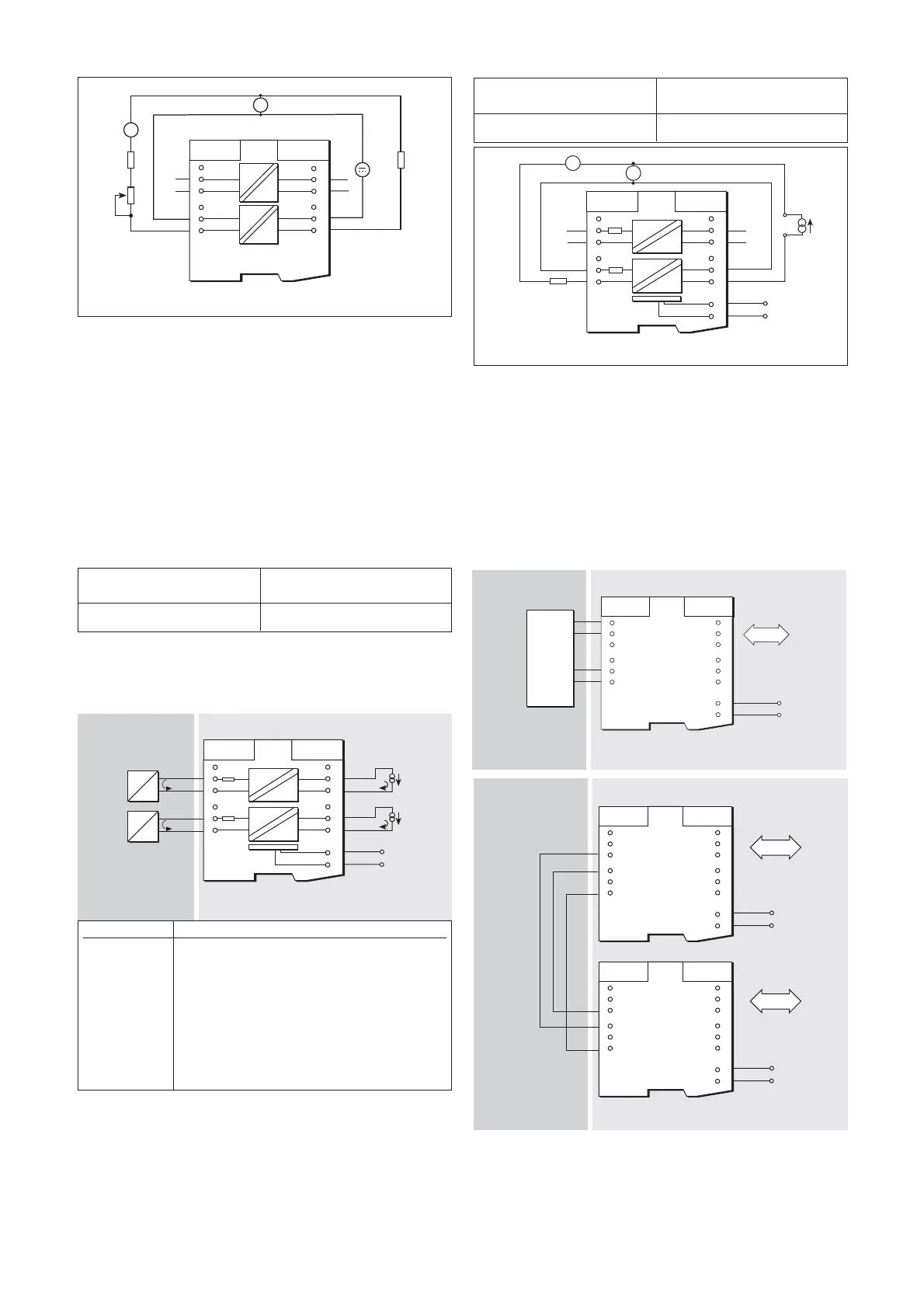
6.23 MTL5049 two-channel isolating driver
The MTL5049 isolates and passes on two 4 to 20mA signals from a
controller located in a safe area to two loads in a hazardous area.
6.23.1 Wiring connections
See figure 6.50 for wiring connections.
6.23.2 Testing
Make the safe- and hazardous-area connections shown in figure 6.51
and, using the current source to vary the output current, carry out the
following checks, first on channel 1 and then on channel 2.
Artisan Technology Group - Quality Instrumentation ... Guaranteed | (888) 88-SOURCE | www.artisantg.com