20
INM5000-6 Jul 2010
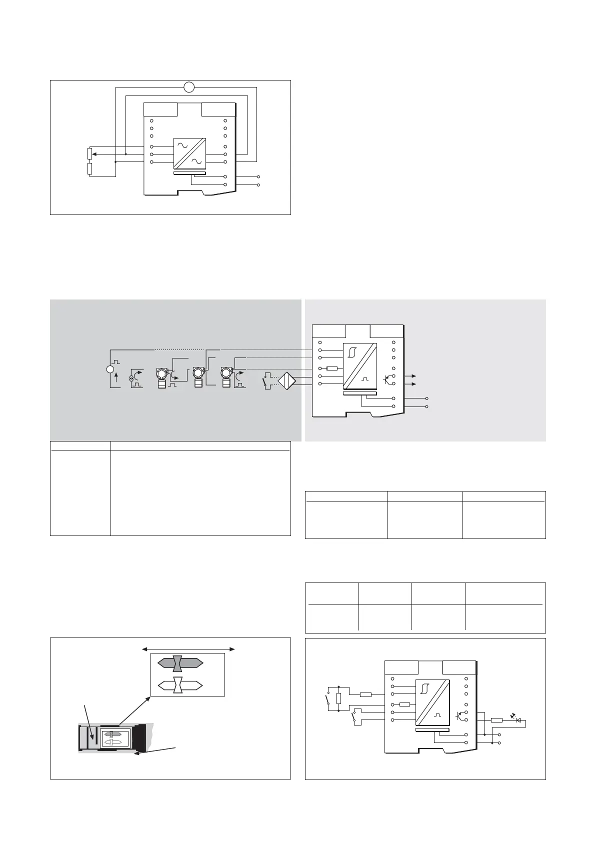
6.15.2 Testing
Make the safe- and hazardous-area connection shown in figure 6.31.
Measure the voltage on terminal 3 with respect to terminal 1; this should
be >19V. Vary the potentiometer setting and check that the reading on
voltmeter V varies by no more than ±100mV.
6.16 MTL5032 pulse isolator
The MTL5032 isolates pulses from a switch, proximity detector, current
pulse transmitter or voltage pulse transmitter located in the hazardous area.
6.16.1. Wiring connections
See figure 6.32 for wiring connections.
*Note: When connected to a circuit which requires an external voltage
or current input, the output may be connected in parallel with that input
in conjunction with a pull-up resistor wired to terminal 12 and connected
to an appropriate voltage source. The zero volt of the same voltage
source should be referenced back to terminal 11. (Maximum current is
50mA; e.g. resistor value of 510
Ω
at 24V.)
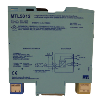
6.16.2 Voltage pulse settings
The threshold voltage for the voltage pulse input is set by two switches
located on the base of the unit. Referring to figure 6.33, these are set
as follows:
6.16.3 Testing
Make the safe- and hazardous-area connections shown in figure 6.34
and carry out the following checks:
Artisan Technology Group - Quality Instrumentation ... Guaranteed | (888) 88-SOURCE | www.artisantg.com