Table 6.10
6.19 MTL5043 repeater power supply
dual output, 4 to 20mA for 2-wire
transmitters
The MTL5043 provides fully-floating dc supplies for a single
conventional 2-wire 4 to 20mA transmitter located in a hazardous area
and driving two safe-area loads. The MTL5043 design changed to
add HART functionality at the end of 2003.
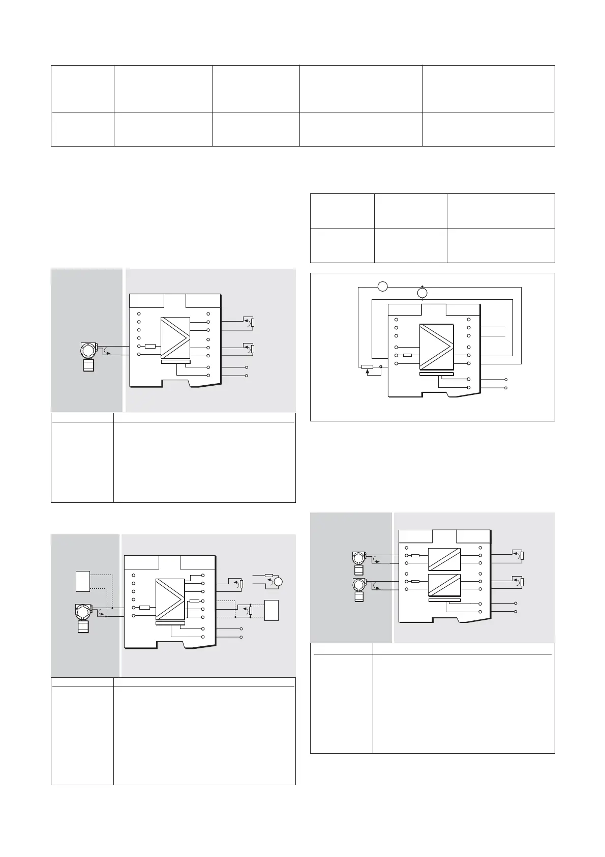
6.19.1 Wiring connections (earlier non-HART version)
See figure 6.40 for wiring connections.
6.19.2 Wiring connections (HART version)
See figure 6.41 for wiring connections.
22
INM5000-6 Jul 2010
Current Current Voltage Voltage
Output reading reading (terminal 2 with respect (terminal 2 with respect
current (A1) (A1) to terminal 1) to terminal 1)
(A2) (MTL5041) (MTL5042) (MTL5041) (MTL5042)
4 to 20mA <±20µA <±10µA — —
20mA — — >16.5V >16.5V
6.19.3 Testing
Make the safe- and hazardous-area connections shown in figure 6.42
and, using RVI to vary the output current, carry out the following checks:
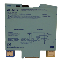
6.20 MTL5044 repeater power supply
The MTL5044 provides fully-floating dc supplies for two conventional 2-
wire 4 to 20mA transmitters located in a hazardous area and repeating
the current in two floating circuits to drive two safe-area loads.
6.20.1 Wiring connections
See figure 6.43 for wiring connections.
Safe area
Figure 6.40: MTL5043 wiring diagram and connections
Hazardous area
Safe area
Hazardous area
Figure 6.41: MTL5043 wiring diagram and connections
Terminal Function
1 Input –ve
2 Input +ve
7 Output –ve (Ch 2 passive current sink)
8 Output –ve (Ch 2 active/+ve current sink)
9 Output +ve (Ch 2 active)
10 Output +ve (Ch 1 via 220Ω for HART apps.)
11 Output –ve (Ch 1)
12 Output +ve (Ch 1)
13 Supply –ve
14 Supply +ve
Artisan Technology Group - Quality Instrumentation ... Guaranteed | (888) 88-SOURCE | www.artisantg.com