31
INM5000-6 Jul 2010
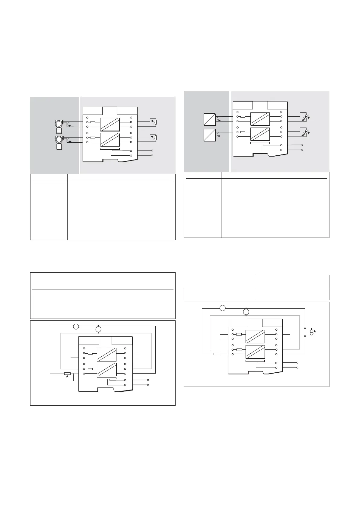
6.33 MTL5344 Repeater power supply
The MTL5344 provides fully-floating dc supplies for two conventional 2-
wire 4 to 20mA transmitters located in a hazardous area and repeats
the current in two floating circuits to drive two safe-area loads.
Note that although this module is similar in function to the MTL5044, the
safety description parameter are very different. Refer to the datasheet
and the ATEX certificate available from the MTL website.
6.33.1 Wiring connections
See figure 6.76 for wiring connections.
6.33.2 Testing
Make the safe- and hazardous-area connections shown in figure 6.77
and, using RV1 to vary the output current, carry out the following checks,
first on channel 1 and then on channel 2:
6
5
4
3
2
1
7
8
9
10
11
12
13
14
I
I
I
I
Ch 2
Ch 1
Vs
Vs+
20 to 35V dc
4/20mA
Load
+
4/20mA
Load
+
+
4/20mA
+
4/20mA
Ch 2
Ch 1
Figure 6.76: MTL5344 wiring diagram and connections
Hazardous area Safe area
Terminal Function
1 Input –ve (Ch 1)
2 Input +ve (Ch 1)
4 Input –ve (Ch 2)
5 Input +ve (Ch 2)
8 Output –ve (Ch 2)
9 Output +ve (Ch 2)
11 Output –ve (Ch 1)
12 Output +ve (Ch 1)
13 Supply -ve
14 Supply +ve
7
8
9
6
5
4
3
2
1
13
14
10
11
12
I
I
I
I
+
+
Ch 1
10k
W
lin
RV1
A1
A2
Ch 1
Ch 2
Ch 2
Vs
Vs+
20 to 35V dc
+
+
Figure 6.77: Test circuit for MTL5344
Output Current Voltage channel 1 Voltage channel 2
current reading (terminal 2 with (terminal 5 with
(A2) (A1) respect to terminal 1) respect to terminal 4)
4 to 20mA <±20µA – –
20ma – >14V –
20ma – – >14V
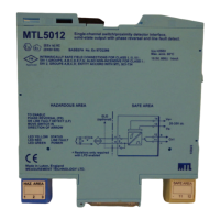
6.34 MTL5349 two-channel isolating driver
The MTL5349 isolates and passes on two 4 to 20mA signals from a
controller located in a safe area to two loads in a hazardous area.
Note that although this module is similar in function to the MTL5049, the
safety description parameter are very different. Refer to the datasheet
and the ATEX certificate available from the MTL website.
6.34.1 Wiring connections
See figure 6.78 for wiring connections.
6.34.2 Testing
Make the safe- and hazardous-area connections shown in figure 6.79
and, using the current source to vary the output current, carry out the
following checks, first on channel 1 and then on channel 2.
6
5
4
3
2
1
7
8
9
10
11
12
13
14
I
I
I
I
P
I
4/20mA
+
P
I
4/20mA
+
+
4/20mA
+
4/20mA
Vs
Vs+
20 to 35V dc
Ch 1
Ch 2
Ch 1
Ch 2
Figure 6.78: MTL5349 wiring diagram and connections
Hazardous area Safe area
Terminal Function
1 Output –ve (Ch 1)
2 Output +ve (Ch 1)
4 Output -ve (Ch 2)
5 Output +ve (Ch 2)
8 Input -ve (Ch 2)
9 Input +ve (Ch 2)
11 Input –ve (Ch 1)
12 Input +ve (Ch 1)
13 Supply –ve
14 Supply +ve
Output Current
current reading (A1)
4 to 20mA <±20μA
6
5
4
3
2
1
7
8
9
10
11
12
13
14
I
I
I
I
Vs
Vs+
20 to 35V dc
A1
A2
+
Current
source
470W
+
+
+
Ch1
Ch2
Ch1
Ch2
Figure 6.79: Test circuit for MTL5349
Artisan Technology Group - Quality Instrumentation ... Guaranteed | (888) 88-SOURCE | www.artisantg.com