30
INM5000-6 Jul 2010
6.32.2 Trip calibration
Switches and multiturn potentiometers for setting the trip points are
located on top of the unit (see figure 6.74). For each of channels A and
B:
i Set trip switch to H (high) or L (low) as required (see table 6.15
for relay operation).
ii Set input current to the required value for trip-point.
iii Adjust SET A/SET B until LED A/B is on: then slowly adjust until
LED goes out.
iv Relays are energised in normal operation and de-energised when
tripped. A lit LED shows the safe condition (not tripped).
Table 6.15
– = Either option ✫ = LED On • = LED Off
6.32.3 Testing
Make the safe- and hazardous-area connections shown in figure 6.75
and carry out the following procedure:
a Set the current source or sink to 12mA
b Adjust each trip potentiometer until the associated LED just
extinguishes.
c With sources of 11.5mA and 12.5mA carry out the following
checks:
6
5
4
3
2
1
7
8
9
10
11
12
13
14
6
5
4
3
2
1
7
8
9
10
11
12
13
14
Vs
Vs+
20 to 35V dc
Trip B
Trip A
Vs
Vs+
20 to 35V dc
+
4/20mA
Load
+
4/20mA
* Hand-held communicator
6
5
4
3
2
1
7
8
9
10
11
12
13
14
I
I
Vs
Vs+
20 to 35V dc
Trip B
Trip A
+
HHC*
HHC*
+
4/20mA
4/20mA
+
+
MTL5314
MTL5042
MTL5314
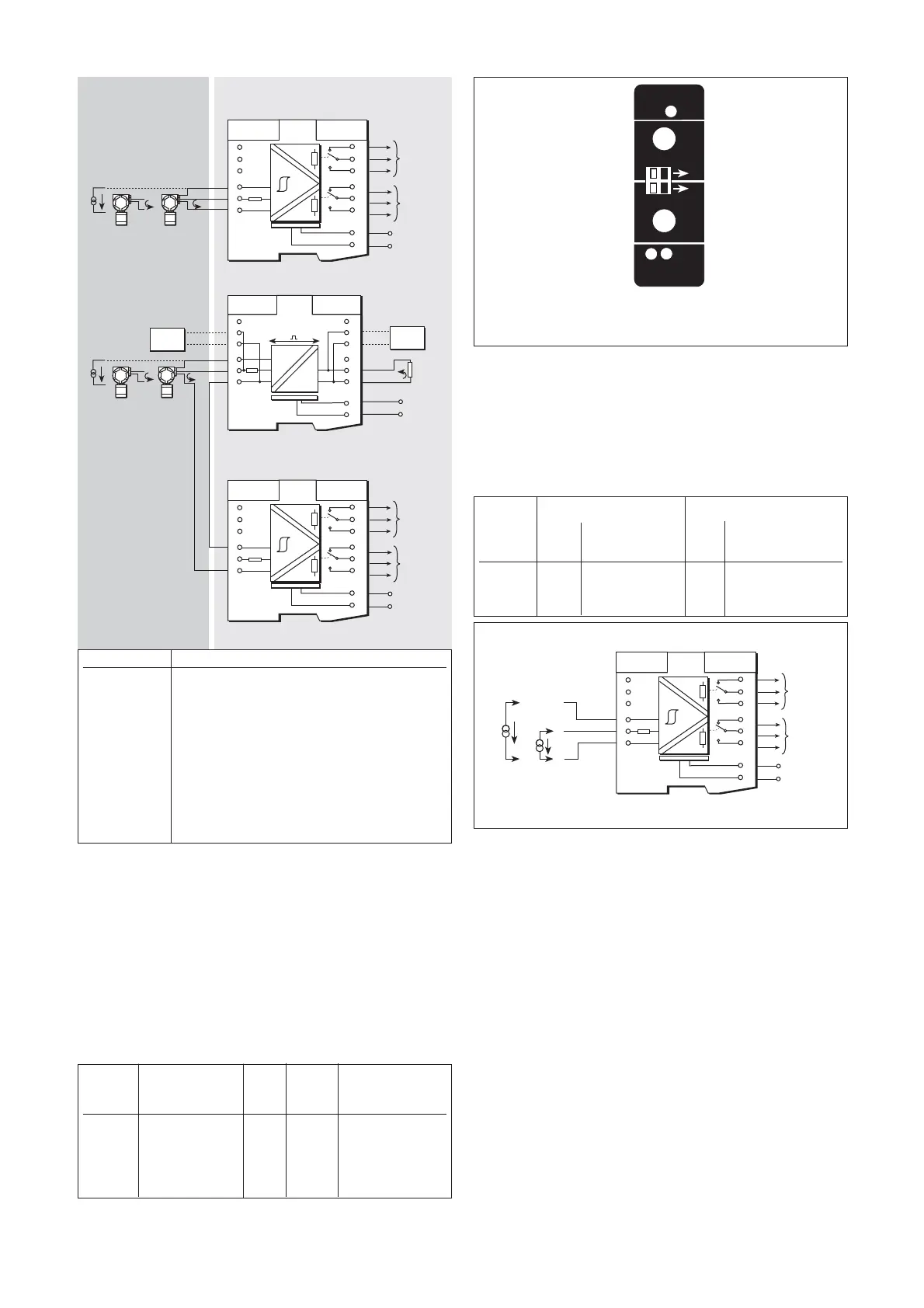
Figure 6.73: MTL5314 wiring diagram and connections
Terminal Function
1 Current input
2 Transmitter supply +ve
3 Common
7 Trip B (NC)
8 Trip B (COM)
9 Trip B (NO)
10 Trip A (NC)
11 Trip A (COM)
12 Trip A (NO)
13 Supply –ve
14 Supply +ve
Hazardous area
Safe area
H
H
SET
A
MTL5314
PWR
LF
PR
CH1
ON
L
L
SET
B
A B
Figure 6.74: Top label, MTL5314, showing positions of trip
switches and multiturn potentiometers
Trip Operation PWR A or B Relay contacts
switch LED LED 11-12 10-11
A or B 8-9 7-8
H (high) Input >Trip setting ✫ • open closed
H (high) Input <Trip setting ✫✫closed open
L (low) Input >Trip setting ✫✫closed open
L (low) Input <Trip setting ✫ • open closed
– – • • open closed
6
5
4
3
2
1
7
8
9
10
11
12
13
14
Vs
Vs+
20 to 35V dc
Trip B
Trip A
Source
or
sink
I
I
+
High alarm Low alarm
Relay Relay
LED 11-12 10-11 LED 11-12 10 -11
Current 8 - 9 7 - 8 8 - 9 7 - 8
11.5mA On Closed Open Off Open Closed
12.5mA Off Open Closed On Closed Open
Figure 6.75: Test circuit for MTL5314
Artisan Technology Group - Quality Instrumentation ... Guaranteed | (888) 88-SOURCE | www.artisantg.com