17
INM5000-6 Jul 2010
6.9.3 Testing
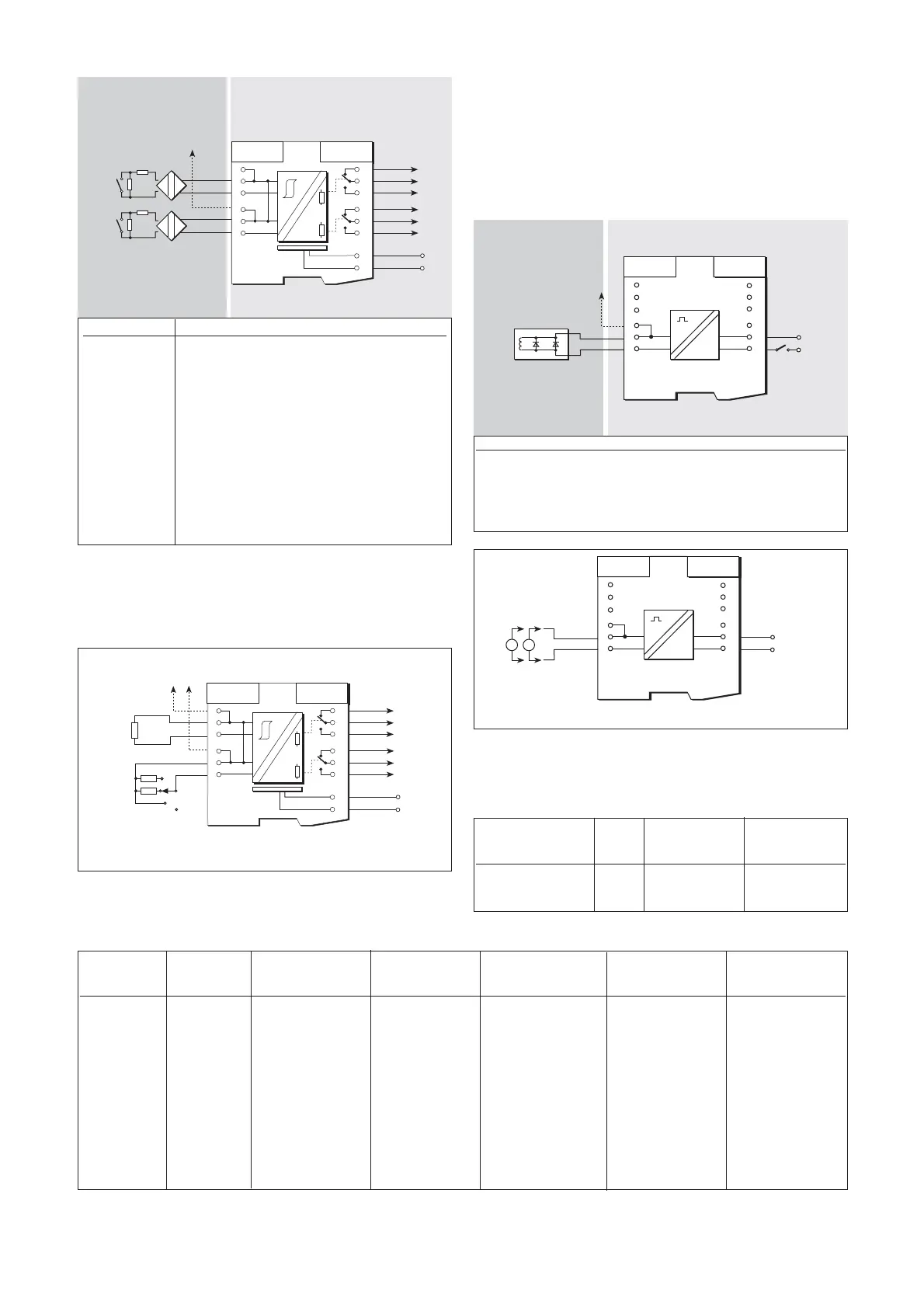
Make the safe- and hazardous-area connections shown in figure 6.19,
and check the status of the output contacts for each channel in turn (with
a 22kΩ resistor connected to the other channel) as shown in table 6.7.
6.10 MTL5021 loop-powered
solenoid/alarm driver, IIC
The MTL5021 enables a device located in the hazardous area to be
controlled by a switch located in the safe area. Suitable for IIC
applications.
610.1 Wiring connections
See figure 6.20 for wiring connections.
6.10.2 Testing
Make the safe- and hazardous-area connections shown in figure 6.19,
apply 24V to terminals 11 and 12 and, with no load, check voltage and
short-circuit current levels at terminals 1 and 2 as follows:
Terminal Function
1 Input –ve (Ch 1)
2 Input +ve (Ch 1)
3 Earth leakage detection
4 Input –ve (Ch 2)
5 Input +ve (Ch 2)
6 Earth leakage detection
7 Normally-closed contact (Ch 2)
8 Common (Ch 2)
9 Normally-open contact (Ch 2)
10 Normally-closed contact (Ch 1)
11 Common (Ch 1)
12 Normally-open contact (Ch 1)
13 Supply N
14 Supply L
6
5
4
3
2
1
7
8
9
10
11
12
13
14
680W
22kW
22kW
To earth leakage
detector
SW
a
b
c
open
+
Ch1
Ch2
Vs
Vs
85 to 265V ac
Ch1
Ch 2
+
Phase Input Output Output Channel Line fault
reverse Line fault switch relay relay status LED LED
switch detection (SW) (11-12, 8-9) (10-11, 7-8) (yellow) (red)
Normal Off a Closed Open On Off
Reverse Off I
sc
= 7 – 9mA Open Closed Off Off
Reverse Off Open Closed Open Off Off
Normal On V
oc
= 7.5 – 9.5V Open Closed Off On
Normal On a Open Closed Off On
Normal On b Open Closed Off Off
Normal On c Closed Open On Off
Input Output Short-circuit
voltage Status voltage current
(terminals 11 & 12) LED (terminals 1 & 2) (terminals 1 & 2)
24V dc On 22 to 24V —
24V dc On — 45 to 52mA
Figure 6.19: Test circuit for MTL5018AC
6
5
4
3
2
1
7
8
9
10
11
12
13
14
Vs
Vs
85 to 265V ac
Ch1
Ch 2
+
22kW
22kW
680W
+
To earth
leakage
detector
Ch 1
Ch 2
680W
Hazardous area Safe area
Figure 6.18: MTL5018AC wiring diagram and connections
7
8
9
10
11
12
6
5
4
3
2
1
Solenoid, alarm or
other IS device
To earth
leakage
detector
20 35Vdc
+
+
Hazardous area
Safe area
Figure 6.20: MTL5021 wiring diagram and connections
Table 6.7
7
8
9
10
11
12
6
5
4
3
2
1
24Vdc
+
+
V
A
Figure 6.21: Test circuit for MTL5021
Terminal Function
1 Output –ve
2 Output +ve
3 Earth leakage detection
11 Supply –ve
12 Supply +ve
Artisan Technology Group - Quality Instrumentation ... Guaranteed | (888) 88-SOURCE | www.artisantg.com