Note: the open circuit window (between 350µA and 50µA) is not
hysteresis, all MTL5000 Series modules with inputs conforming to
NAMUR/DIN 19234 will switch between open and complete circuit
conditions within these limits.
Note: the short circuit window (between 100
Ω
and 360
Ω
) is not
hysteresis, all MTL5000 Series modules with inputs conforming to
NAMUR/DIN 19234 will switch between open and complete circuit
conditions within these limits.
Modules with LFD and inputs conforming to NAMUR/DIN
19234:
MTL5011B, 5014* and 5018: LFD enable switch on top label
* The MTL5014 has a Slave/LFD output relay arrangement
(see module description in section 6).
MTL5012 and 5015: LFD enable switch on top label
MTL5017: LFD permanently enabled
Other modules with LFD facility
MTL5023 solenoid/alarm driver: LFD automatic
MTL5046 isolating driver: LFD automatic
Note: The safe-area circuit impedance will increase with hazardous-
area load and will rise >150kΩ for the 'open circuit' line fault.
MTL5113x: LFD automatic
Hazardous-area load Safe-area input
<50Ω High impedance (>150kΩ)
>90Ω Normal operation
Hazardous-area input (either channel) Line-fault-detect relay
<50µA De-energised
>350µA Energised
>360Ω Energised
<100Ω De-energised
LFD switch setting Hazardous-area input(s) Solid-state output(s)
On <50µA Non-conducting
On >350µA Conducting
On >360Ω Conducting
On <100Ω Non-conducting
LFD switch setting Hazardous-area input(s) Output relay(s)
On <50µA De-energised
On >350µA Energised
On >360Ω Energised
On <100Ω De-energised
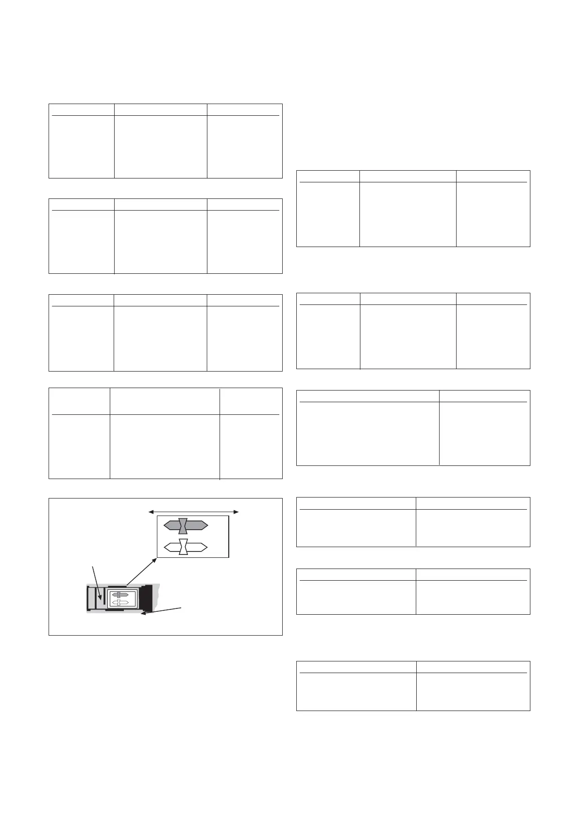
3.1.3 Phase reversal
Switch(es) to change the phase of the output(s) relative to the input(s) are
provided on the top labels of some of the MTL5000 Series modules and
on the base of others. The following applies:
MTL5011B, 5014 and 5018: Phase reversal switch on top label
MTL5017: Phase reversal switch on base of module
MTL5012 and 5015: Phase reversal switch on top label
MTL5023 and 5024: Phase reversal switch on base of module
Positions for base-located switches are set as shown in figure 3.4.
3.1.4 Line fault detection (LFD)
Line fault detection on hazardous-area sensor lines (open circuit or short
circuit) is provided on some MTL5000 Series modules.
Note: resistors must be fitted when using the LFD facility with a contact
input: 500
Ω
to 1k
Ω
in series with switch and 20k
Ω
to 25k
Ω
in parallel
with switch.
For hazardous-area inputs conforming to NAMUR/DIN
19234, a line fault condition is indicated as follows:
Open circuit condition if hazardous-area current <50µA
Line integrity (no open circuit) if hazardous-area current >350µA
Short circuit condition if hazardous-area load <100Ω
Line integrity (no short circuit) if hazardous-area load >360Ω
3
INM5000-6 Jul 2010
PR switch setting Hazardous-area input(s) Output relay(s)
Off <1.2mA De-energised
Off >2.1mA Energised
On <1.2mA Energised
On >2.1mA De-energised
PR switch setting Hazardous-area input(s) Solid-state output(s)
Off <1.2mA Non-conducting
Off >2.1mA Conducting
On <1.2mA Conducting
On >2.1mA Non-conducting
Hazardous-area
PR switch setting Safe-area control output
o ← (off) CTRL+Ve >4.5V above CTRL-Ve Enabled
o ← (off) CTRL+Ve <1.4V above CTRL-Ve Disabled
→ + (on) CTRL+Ve >4.5V above CTRL-Ve Disabled
→ + (on) CTRL+Ve <1.4V above CTRL-Ve Enabled
Hazardous-area load Solid-state LFD output
<50Ω Non-conducting
>7kΩ Non-conducting
Hazardous-area input LFD output
< 50µA (open-circuit) de-energised
> 6.6mA (short-circuit) de-energised
Figure 3.4: Phase reversal switch on base of units
PR switch setting Hazardous-area input(s) Output relay(s)
o ← (off) <1.2mA De-energised
o ← (off) >2.1mA Energised
→ + (on) <1.2mA Energised
→ + (on) >2.1mA De-energised
Artisan Technology Group - Quality Instrumentation ... Guaranteed | (888) 88-SOURCE | www.artisantg.com