7. Begin to lift the electronic assembly out of the enclosure. To fully remove the electronic assembly it will be nec-
essary to disconnect the heater cable, 4-20 milliamp cable, the AC ground cable and the intrinsic safety barrier
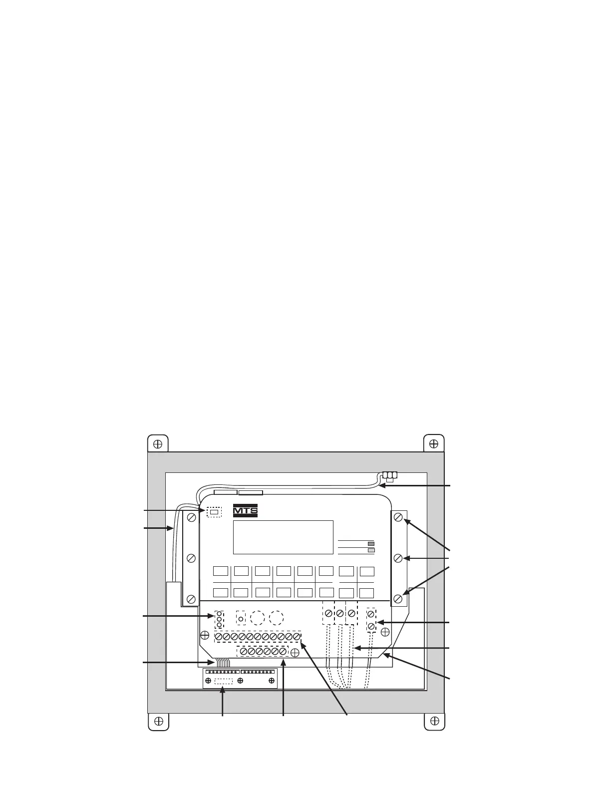
ground cable. The heater cable can be unplugged from the connector (P3) located at the top left corner behind
the keypad panel. The 4-20 milliamp cable can be disconnected from the connector located on the lower left
corner of the 4-20 milliamp PCB. The AC ground cable can be removed from the ground stud inside the NEMA
7 enclosure. The intrinsic safety barrier ground can be removed from the ground lug located under the terminal
block cover. See illustration D-3 for connector locations.
8. After all cables have been disconnected, carefully remove the electronic assembly completely from the NEMA 7
enclosure. Be extremely careful not to damage the keypad ribbon cables exiting from the top left corner of the
keypad. Place the removed electronic assembly on a clean working surface or bench.
9. The EPROMs are the two labeled integrated circuits installed in the latching sockets on the rear of the electron-
ics assembly. Remove one EPROM at a time by releasing the latching mechanism on the socket. The latching
mechanism is released by carefully pushing the latching levers away from the body of the EPROM into the hor-
izontal position. The levers will lift the EPROM from the socket.
10. Install the new EPROMs into the sockets. Note that each EPROM is numbered (-1 or -0) and must be installed in
the respective socket and oriented properly. The small indentation on the end of each EPROM must be orient-
ed as shown in illustration D-4.
11. Visually inspect the newly installed EPROMs to insure all 28 pins are properly seated in the sockets and that the
orientation is correct. Compare to illustration D-4.
12. Reinstall the electronic assembly into the NEMA 7 enclosure. The installation is performed in the reverse order
of the removal. Insure that all cables and customer wiring are properly reinstalled.
13. Reinstall the six screws to secure the electronic assembly to the aluminum brackets. It may be necessary to loosen
the four screws securing the brackets to the back of the NEMA 7 enclosure to realign the brackets. Retighten all
screws.
14. Reconnect AC power and check for proper monitor operation.
Figure D-3. NEMA 7 Mounting Screws & Cables Locations