6 The Control Panel
The Level Plus control panel is shown in Figure 3.
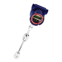
Figure 3. Level Plus Control Panel
The control panel includes LED’s for power and alarm indication, a LCD screen displaying 4 lines
of 20 characters each, 12 numeric keys, and 4 control keys.
In program mode, the number keys (0 to 9, ±, and •) are used
to enter numeric values for programmable parameters. In mea-
surement mode, the number keys are used to access tank
gauge measurement data and to change the basic display
modes provided by the software.
The green Power LED and red Alarm LED are located at the right side of
the control panel. The Power LED is lit when the monitor is connected to
power and Switch S1 is in the ON (up) position. The red Alarm LED
flashes to indicated an alarm condition.
?
?
?
?@@@@6X
?@@??@1
?@@??@5
?@@@@0Y
?@@?e?
?@@?e?
?@@?e?
?
?
?W2@@@
?7@??@
?@@??@
?3@??@
?V4@@@
?
?
?
?
?
@@6?2@@@@@@@6?2@@
N@@@@@@@@@e@@@@5
?@@@@@@@@@@@@@@@H
?3@@@@@@@@f@@?
?V40?40MI4@@@@@@?
?
?
?@@?e@@
J@@Le@@
7@@1e@@@@@@6X?@@@@@@@@@6X
?J@@@@L?@@f@1?@@@@@?@@?@1
?7@@@@1?@@W2@@@@?@@?@@?@@?@@
J@@??@@?@@@@e@@?@@?@@?@@?@@
@@@??@@@@0?4@@@@?@@?@@?@@?@@