95
Appendix D
EPROM Replacement Procedure
NEMA 1 Model
1. Disconnect AC power from the Level Plus monitor at the main fuse panel.
2. Remove the EPROM access cover located on the rear of the NEMA 1 enclosure (1 screw).
3. The EPROM's are the two labeled integrated circuits installed in the latching sockets. Remove one eprom at a
time by releasing the latching mechanism on the socket. The latching mechanism is released by carefully push-
ing the latching levers away from the body of the EPROM into the horizontal position. The levers will lift the
eprom from the socket.
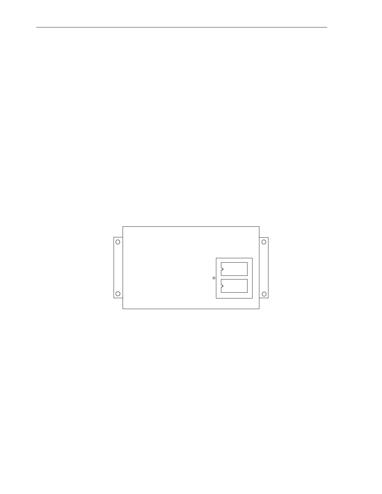
4. Install the new EPROM into the socket. Note that each EPROM is numbered (-1 or -0) and must be installed in
the respective socket and oriented properly. The small indentation on the end of each EPROM must be orient-
ed as shown in illustration D-1.
5. Visually inspect the newly installed EPROM's to insure all 28 pins are properly seated in the sockets and that the
orientation is correct. Compare to illustration D-1 shown below.
6. Reinstall the EPROM access cover.
7. Reconnect AC power and check for proper monitor operation.
Figure D-1. NEMA 1 EPROM orientation
NEMA 4X Model
1. Disconnect AC power from the Level Plus monitor at the main fuse panel.
2. The main electronics assembly must be removed from the NEMA 4X enclosure to gain access to the EPROM
devices. Follow steps 3 through 9 to remove the main electronic assembly.
3. Disconnect the AC power terminations at terminal block TB1.
4. Disconnect any customer terminations to the relay contacts (TB3) and to the communication interface (TB2).
Terminal blocks TB2 and TB3 are of the pluggable type.
5. Disconnect any customer terminations to the 4-20 milliamp terminal block. The 4-20 milliamp terminal block is
of the pluggable type.
6. Disconnect the tank gauge field wiring from intrinsic safety barriers.