16
7. Analog Personality Module
The Analog Personality Module (APM) is mounted inside the electronics housing of the Temposonics II linear dis-
placement transducer and produces a direct analog output. No additional interfacing electronics are required. The
APM processes digital data into an analog output via a digital to analog converter (DAC). MTS uses a 16-bit DAC
to provide the best available resolution performance.
Typically the APM will be ordered with the Temposonics II transducer. The APM is installed, and the set points
and output voltages are pre-set at the factory.
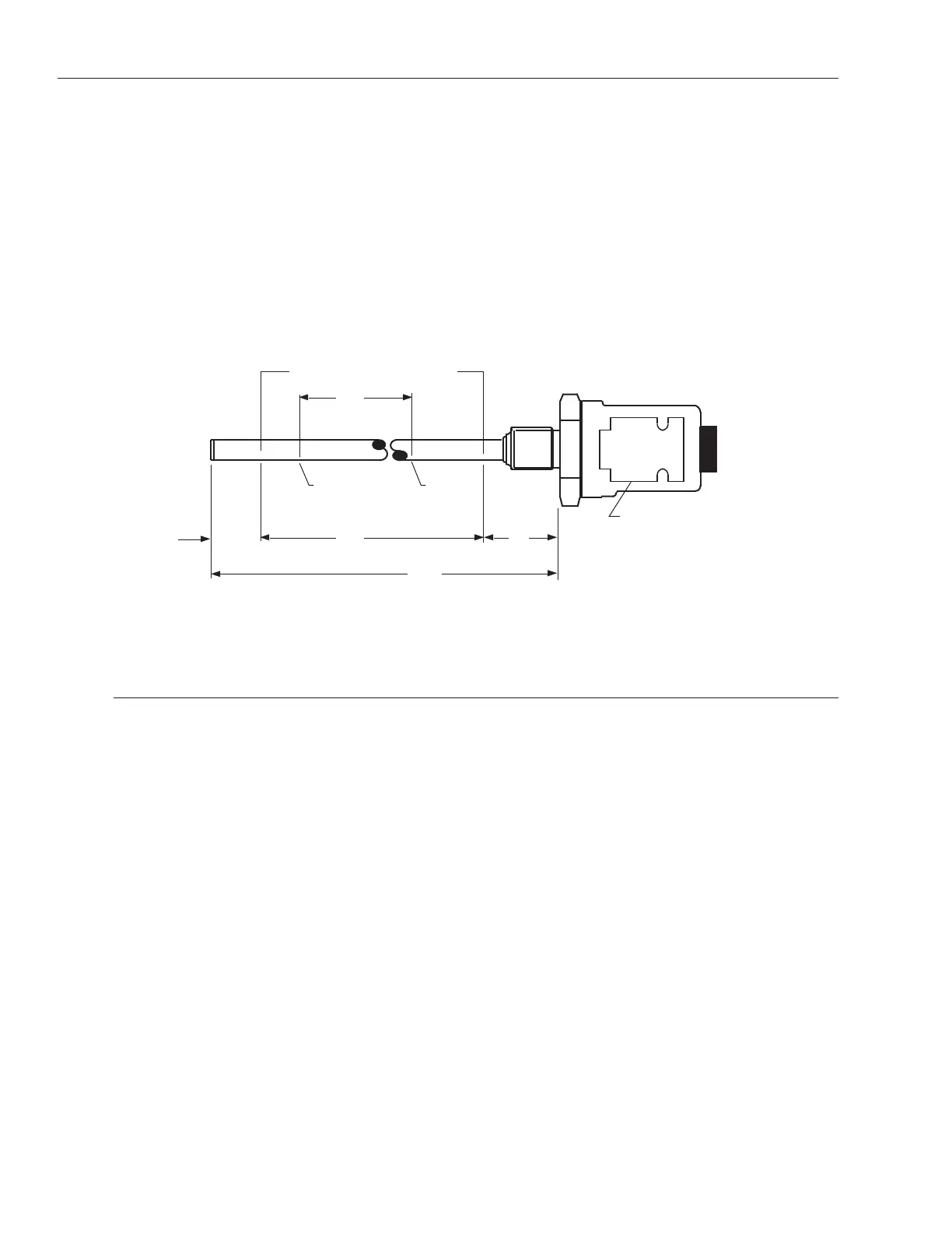
In the example below (Figure 7-1) we have a 60 inch stroke, note the indicated active stroke range. Set points
cannot be set within the null or dead space area, they can only be set within the active stroke area. The 13 inch
stroke selected in the example is defined by Set Point 1 (set at 4.000 volts) and Set Point 2 (set at 7.538 volts). Set
Point voltage values can range from -10 to +10 Vdc.
Figure 7-1
Voltage & Displacement - 100% Scalable.
7.1 Performance Modes
Update time (or response time) for analog systems is based upon the active stroke of the transducer and
the resolution desired. To get the best mix of update time and resolution for your particular application,
three modes are available with the APM. These modes are as follows:
Resolution-Preferred Mode - In this mode the APM generates a high resolution output while
sacrificing update time. The Resolution Preferred Mode is limited to stroke lengths up to 48 inch-
es and will provide an output resolution of approximately 0.001 inches. In applications exceeding
48 inches, the APM must be set for Balanced Mode or Update Preferred Mode. In the program-
ming procedure, the Resolution Preferred Mode is indicated by an output of 0 volts.
Balanced Mode - In this mode the APM offers a "balance" between update time and resolution.
For stroke lengths up to 250 inches, the output resolution will be approximately 0.003 inches. In
the programming procedure, this mode is indicated by an output of +8.4 volts.
Update Preferred Mode - In this mode the APM produces the fastest possible update time while
sacrificing resolution. For stroke lengths up to 300 inches, the output resolution will be approxi-
mately 0.007 inches. In the programming procedure, this mode is indicated by an output of -8.4
volts.
 Loading...