8. Installing the Analog Output Module (AOM)
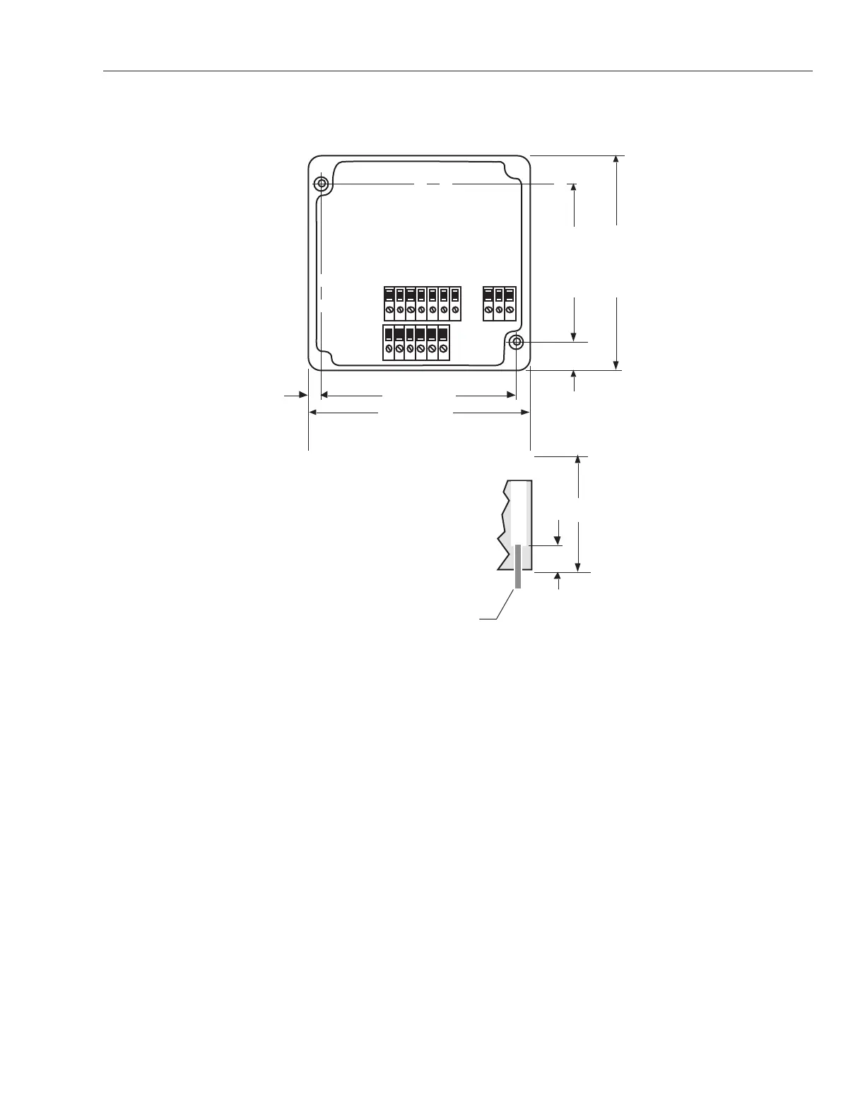
Dimensions of the AOM are shown below in Figure 8-1. The mounting hole dimensions shown are also stamped
on the back of the module. Mount the AOM as shown, using two socket head cap-screws.
Figure 8-1
AOM Dimensions
1. Mount the AOM in a location within reach of the LDT assembly cable. Standard systems allow the AOM to be
mounted 250 feet from the LDT assembly.
2 Connect cable from AOM to the LDT assembly.
3. Adjust the AOM null and full-scale potentiometers (as described in Section 9) to compensate for any offsets due
to mechanical installation.
0.24 in.(6.1 mm)
0.52 in.
(13.2 mm)
3.88 in.(98.6 mm)
3.31 in.(84.1 mm)
4.35 in.(110.5 mm)
4.35 in.(110.5 mm)
2.25 in. (57.1 mm)
with Cover
0.5625 in.
(14.3 mm)
Socket Head Cap Screw (2)
10-32 UNF-2A thread x 3/4 in. lg. (Recommended)
(Shown with Cover Removed)
TB2
TB3TB1
H J K
A B C D E F
GA B C D E F
 Loading...