27
10.3 J1 Connections for AOM
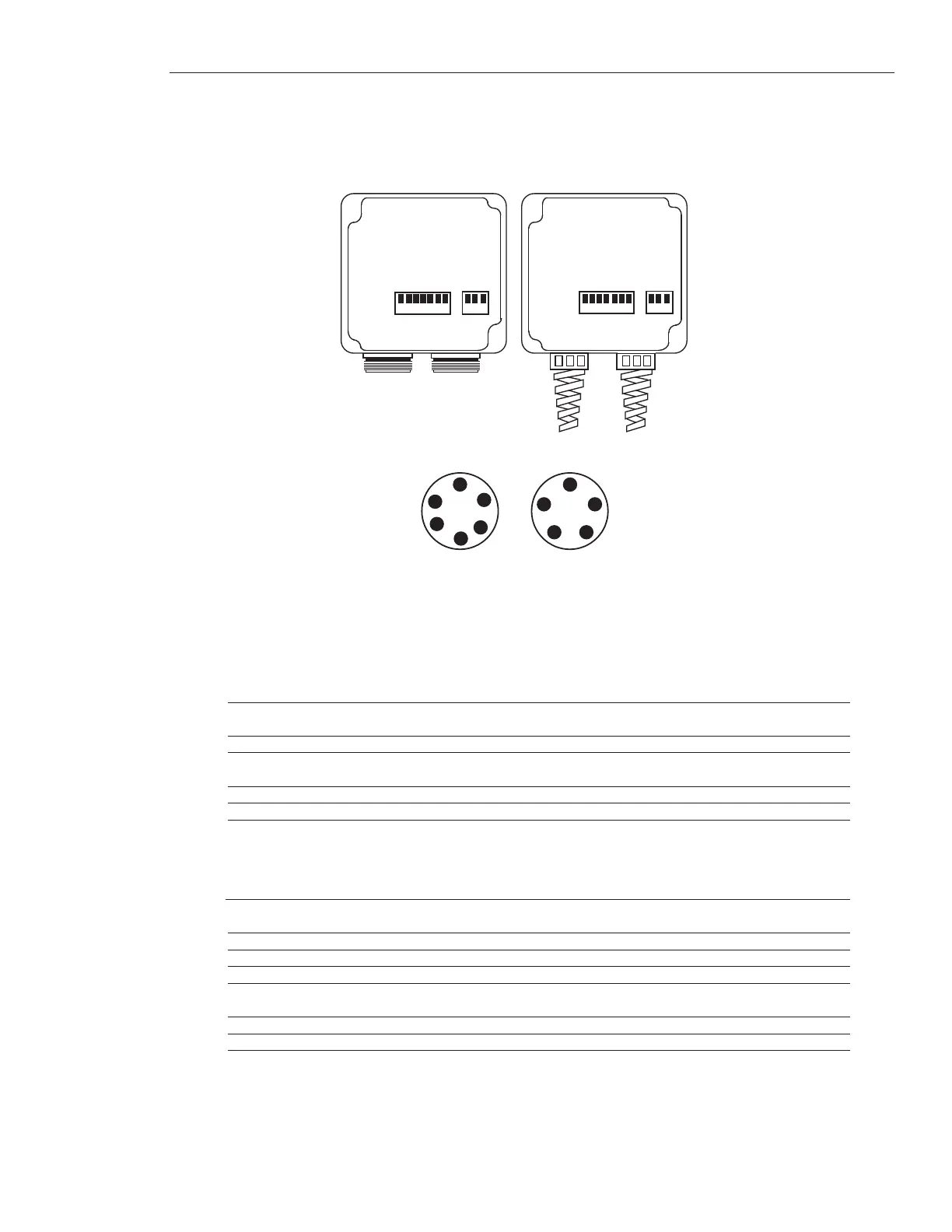
The AOM is provided with either a strain relief connector, which accepts a pigtailed connection directly
into terminals blocks located inside the AOM enclosure, or a threaded MS connectors. Tables 10A through
10F, below, indicate the appropriate connection to make for either configuration. Make sure that you fol-
low the appropriate table for your specified options.
Figure 10-2
AOM w/ Strain Relief and MS Connectors
Table 10A Standard J1 Connections
Strain Relief Connection MS Connector Pin Designation (J1) Function
TB1
A D Displacement Output
B E Displacement Output Return (ground)
TB3
H A + 15 Vdc
J B - 15 Vdc
K C DC Common
Table 10B J1 Connections w/Velocity Output Option
Strain Relief Connection MS Connector Pin Designation (J1) Function
TB1
A D Displacement Output
B - Displacement Output Return (ground)
C E Velocity Output
D - Velocity Output Return (ground)
TB3
H A + 15 Vdc
J B - 15 Vdc
K C DC Common
 Loading...