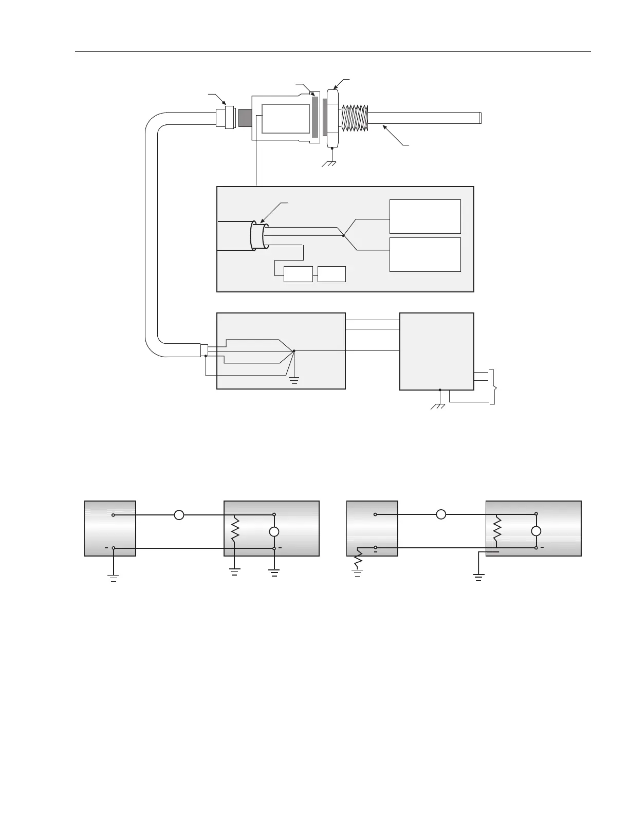
5. Grounding
Figure 5-1
Grounding
Figure 5-2 Figure 5-3
4-20mA Grounded Loop 4-20mA Ungrounded Loop
NOTES FOR FIGURES 5-2 & 5-3:
1. Selecting the grounding scheme is dependent upon the controller interface.
2. The current loop path must be completed for the system to operate.
3. The ungrounded loop is not truly isolated from ground. Isolators are required if this configuration is needed by the controller interface.
Signals Return(s)
Power Return
Frame
Bracket Cover
Cable Shield (no connection)
Head Assembly Grounding Diagram
Signals Return(s)
Power Return
Frame
+Vcc
-Vee
Control Module
(AOM, DIB, Counter Card or other)
(internal to
head enclosure)
Connector
(10 pins)
Ground connection between bracket
and outer cover made by threads
Transducer Rod
(3/8 in. stainless steel)
Machine Ground
Flange
(electrically isolated from threads)
Power Return
Shield Ground
(non current carrying)
AC Line
Bracket
Power Supply
Driver/Amplifier
Module
Option Module
 Loading...