EasyManuals Logo

MTS Systems Temposonics II LDT Installation Instructions Manual

Default Icon
41 pages
To Next Page IconTo Next Page
To Previous Page IconTo Previous Page
Page #17 background imageLoading...
Page #17 background image
14
6. Introduction to Analog Systems
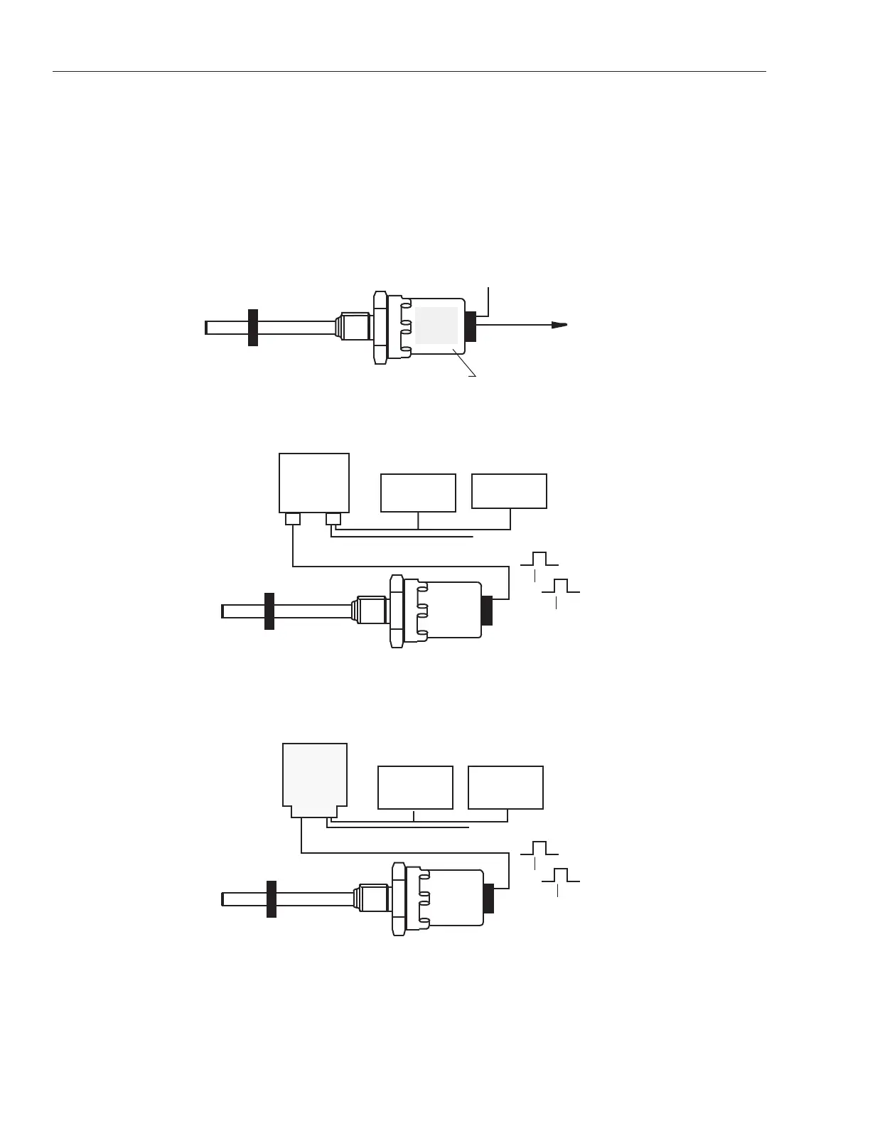
Temposonics II Analog Systems include a Linear Displacement Transducer (LDT), a magnet, and an Analog
Personality Module (APM), Analog Output Module (AOM), or an Analog Output Card. See Figures 6-1, 6-2 and 6-
3. The APM, AOM and Analog Output Card generate the interrogation pulse, sense the return pulse, and develop
the analog output displacement signal (voltage or current).
The Analog Personality Module (Figure 6-1) is installed in the electronics enclosure of the Temposonics II trans-
ducer. The Analog Output Module and Analog Output Card are both separate interface devices.
Figure 6-1
Analog System Configuration with Analog Personality Module
Figure 6-2
Analog System Configuration
with Analog Output Module (AOM)
Figure 6-3
Analog System Configuration
with Analog Output Card
POWER SUPPLY
+ 15 Vdc / 250 mA
- 15 Vdc / 65 mA
Analog Displacement Output
Belden YR8105 or equivalent (5 pairs)
T1
T2
Magnet
Temposonics II LDT
ANALOG
OUTPUT
CARD
OPTIONAL
24Vdc @ 340 mA
T1
T2
ANALOG
OUTPUT
MODULE
(AOM)
J1J2
Analog Displacement Output
Belden YR8105 or equivalent (5 pairs)
POWER SUPPLY
+ 15 Vdc / 250 mA
- 15 Vdc / 65 mA
OPTIONAL
24 Vdc@ 340 mA
Magnet
Temposonics II LDT
APM
Analog Personality Module
USER'S
CONTROL
SYSTEMOutput:
To be specified
Range: - 10 to + 10 Vdc
POWER SUPPLY
± 13.5 to ±15 Vdc@ 190 mA
(bipolar)
Magnet
Temposonics II LDT

Other manuals for MTS Systems Temposonics II LDT

Questions and Answers:

Question and Answer IconNeed help?

Do you have a question about the MTS Systems Temposonics II LDT and is the answer not in the manual?

MTS Systems Temposonics II LDT Specifications

General IconGeneral
BrandMTS Systems
ModelTemposonics II LDT
CategoryTransducer
LanguageEnglish