Temposonics
®
R-Series V Analog
Operation Manual
I 16 I
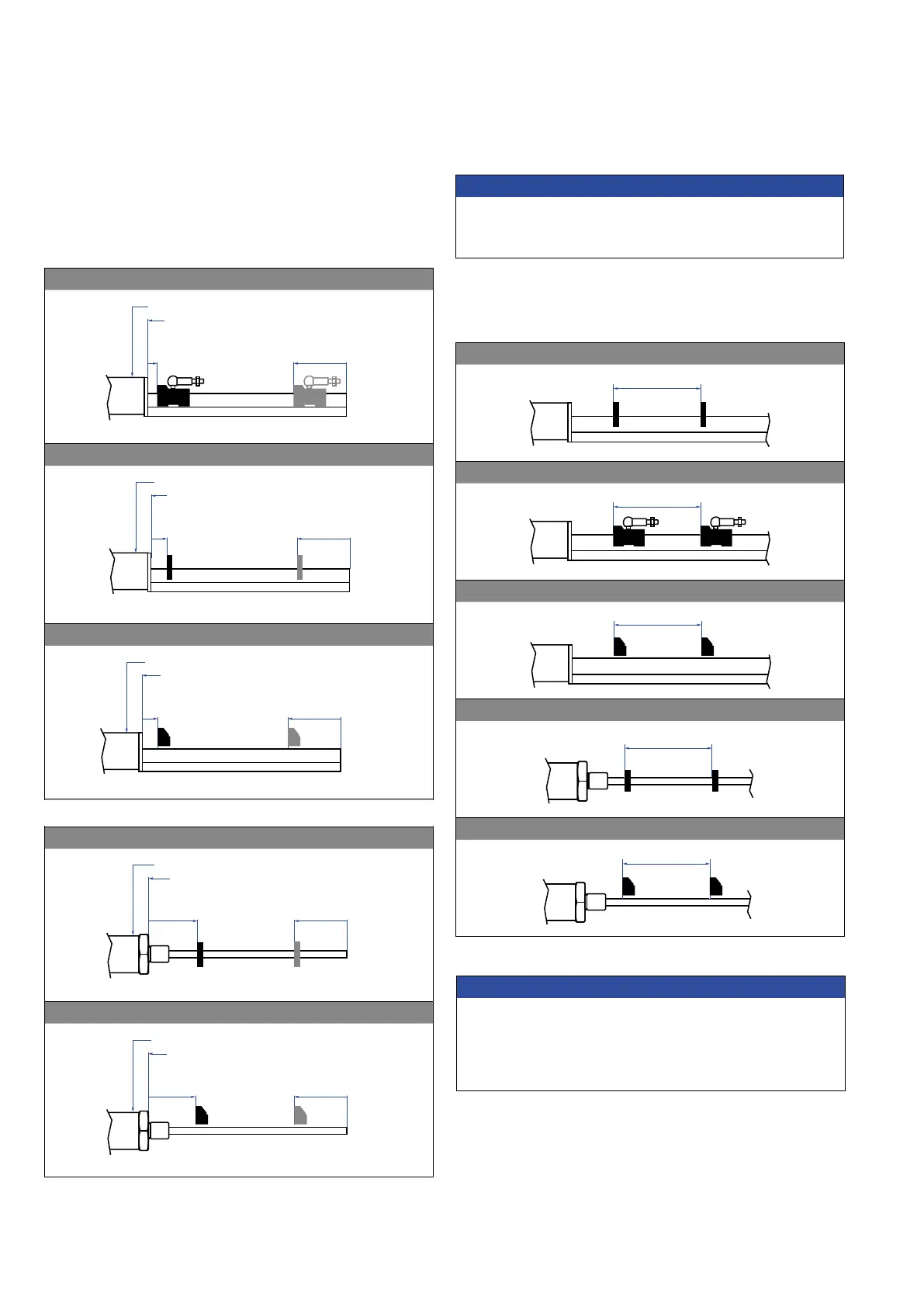
Fig. 17: Start- & end positions of magnets for RP5
Fig. 18: Start- & end positions of magnets for RH5
RP5 with magnet slider “S”, “N”, “V”, “G”
Sensor electronics housing
Reference edge of mounting
Start position
12 (0.47)
End position
82 / 87* (3.23 / 3.43*)
* Stroke length > 5000 mm (196.9 in.)
RP5 with U-magnet
Reference edge of mounting
Sensor electronics housing
Start position
28 (1.1)
End position
* Stroke length > 5000 mm (196.9 in.)
RP5 with block magnet
Reference edge of mounting
Sensor electronics housing
* Stroke length > 5000 mm (196.9 in.)
End position
68.5 / 73.5* (2.7 / 2.9*)
Start position
25.5 (1)
RH5 with ring magnet/U-magnet
Sensor electronics housing
Reference edge of mounting
Start position
51 (2.01)
End position
63.5 / 66* (2.5 / 2.6*)
* Stroke length > 5000 mm (196.9 in.)
Sensor electronics housing
Reference edge of mounting
Start position
48.5 (1.91)
End position
66 / 68.5* (2.6 / 2.7*)
* Stroke length > 5000 mm (196.9 in.)
RP5 with magnet slider “S”, “N”, “V”, “G”
Sensor electronics housing
Reference edge of mounting
Start position
12 (0.47)
End position
82 / 87* (3.23 / 3.43*)
* Stroke length > 5000 mm (196.9 in.)
Reference edge of mounting
Sensor electronics housing
Start position
28 (1.1)
End position
66 / 71* (2.6 / 2.8*)
* Stroke length > 5000 mm (196.9 in.)
Reference edge of mounting
Sensor electronics housing
* Stroke length > 5000 mm (196.9 in.)
End position
68.5 / 73.5* (2.7 / 2.9*)
Start position
25.5 (1)
RH5 with ring magnet/U-magnet
Sensor electronics housing
Reference edge of mounting
Start position
51 (2.01)
End position
63.5 / 66* (2.5 / 2.6*)
* Stroke length > 5000 mm (196.9 in.)
RH5 with block magnet
Sensor electronics housing
Reference edge of mounting
Start position
48.5 (1.91)
End position
66 / 68.5* (2.6 / 2.7*)
* Stroke length > 5000 mm (196.9 in.)
NOTICE
On all sensors, the areas left and right of the active stroke length are
provided for null and dead zone. These zones should not be used for
measurement, however the active stroke length can be exceeded.
Start- and end positions of the position magnets
Consider the start and end positions of the position magnets during
the installation. To ensure that the entire stroke length is electrically
usable, the position magnet must be mechanically mounted as follows.
Multi-position measurement
The minimum distance between the magnets is 75 mm (3 in.).
Fig. 19: Minimum distance for multi-position measurement
RP5 with U-magnets
RP5 with magnet sliders
RP5 with block magnets
RH5 with ring magnets/U-magnets
RH5 with block magnets
NOTICE
For multi-position measurement, use magnets of the same type
e.g. 2 × U-magnet (part no. 251 416-2).
Do not fall below the minimum distance between the magnets of
75mm (3 in.) for multi-position measurement. Contact MTS Sensors
if you need a magnet distance < 75 mm (3 in.).
 Loading...
