Temposonics
®
R-Series V Analog
Operation Manual
I 17 I
Controlling design dimensions are in millimeters and measurements in ( ) are in inches
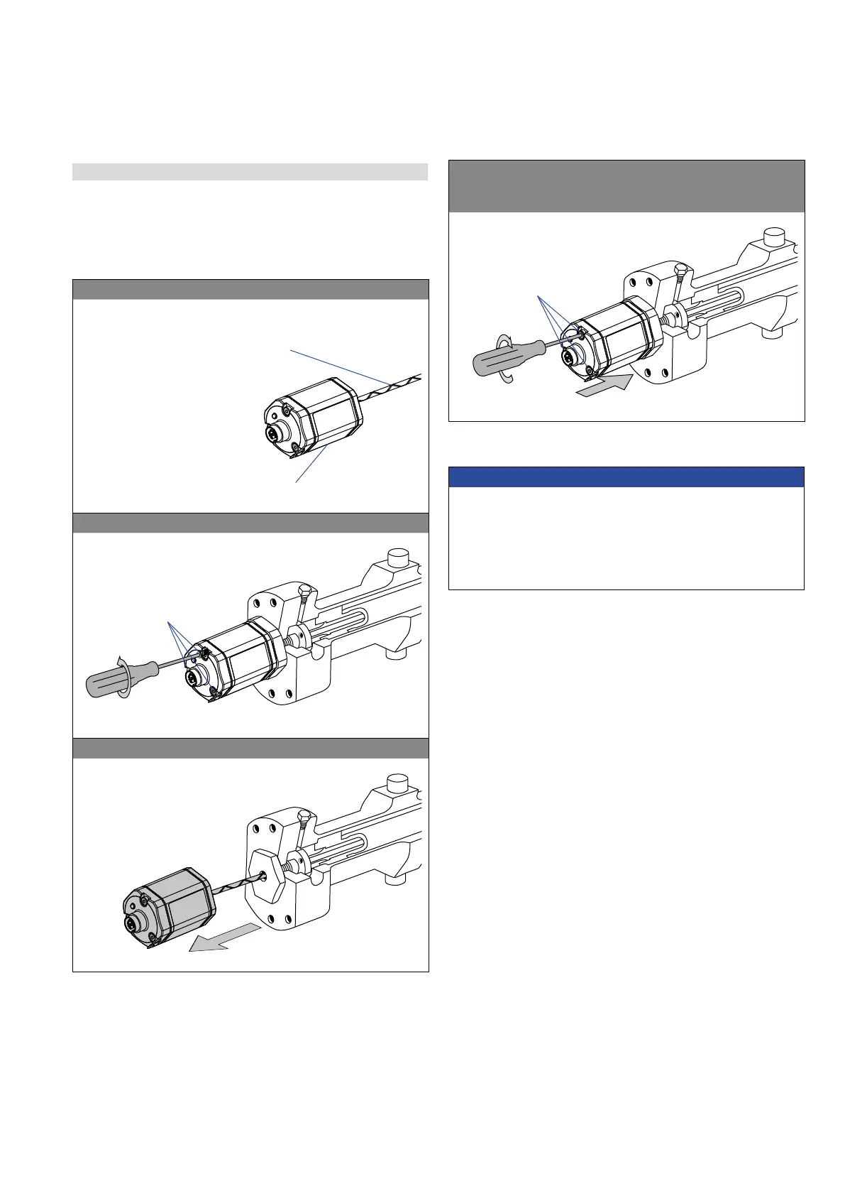
Fig. 20: Replacement of the base unit (e.g. RH5 sensor), part 1
Base unit
Sensor electronics housing
Tube with inner sensor element
1. Loosen the screws.
3 × socket head screw
M4 (A/F 2.5)
2. Pull out the base unit.
4.5 Replacement of base unit
The base unit of the sensor model RH5 (RH5-B) is replaceable as
shown in Fig. 20 and Fig. 21 for the sensor designs »M«, »S« and
»T«. The sensor can be replaced without interrupting the hydraulic
circuit.
3. Insert the new base unit.
Install the ground lug on a screw.
Tighten the screws.
Fastening torque
1.4 Nm
Fig. 21: Replacement of the base unit (e.g. RH5 sensor), part 2
NOTICE
• If the R-Series V replaces a predecessor model of the R-Series,
the plastic tube in the sensor rod must be removed.
• When replacing the base unit, make sure that no humidity enters
the sensor tube. This may damage the sensor.
• Secure the base unit screws, e.g. using Loctite 243, before
re-installing.
 Loading...
