Temposonics
®
R-Series V Analog
Operation Manual
I 25 I
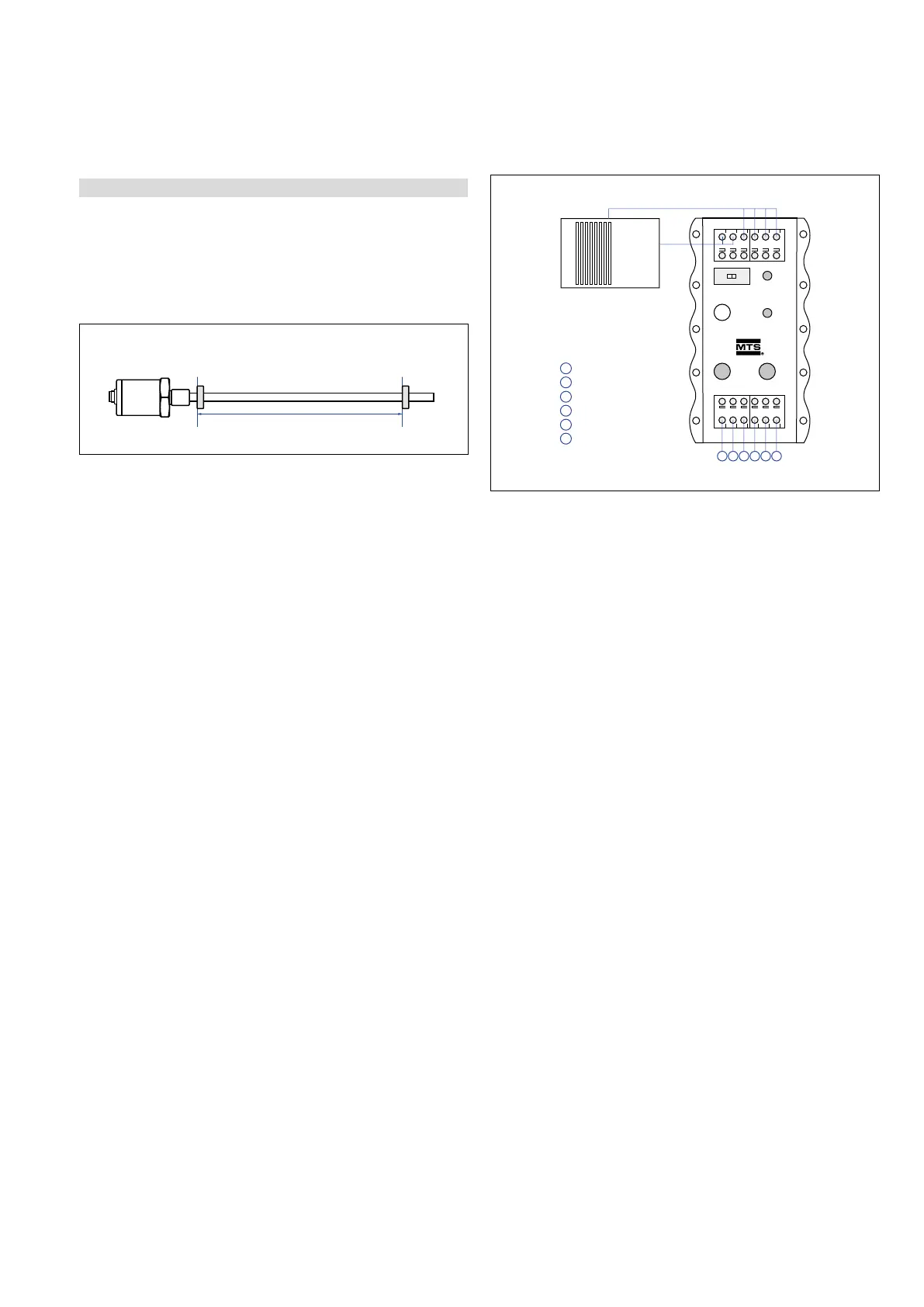
5.4.2 Programming via cabinet programmer for analog output
Cabinet programmer for analog output (part no. 253 408), connected
between sensor and control unit is provided for setup of measuring
range by moving the magnet on desired Null/Span positions
(minimum distance between setpoints: 25 mm) and pushing the
corresponding 0 % respectively 100 % buttons on programmer.
PLCSENSOR
Program /Run
Start
0 %
100 %
Programming mode
24 VDC
Out 1 / Pin 1, GY
GND 1 / Pin 2, PK
Out 2 / Pin 3, YE
GND 2 / Pin 4, GN
24 VDC / Pin 5, BN
GND / Pin 6, WH
123456
1
2
3
4
5
6
Power supply
Fig. 31: Connecting the programmer
1 Magnet position
Active measuring range
1 Magnet sensor
Output 1: position
0 % 100 %
2 Magnets
Active measuring range
min. 76 mm
0 % 100 %
2 Magnet sensor
Output1: Position magnet 1, Output 2: Position magnet 2
Fig. 32: Connecting sensor with cabinet programmer
Mounting
The programmer electronics housing is designed for snap-in mounting
on standard 35 mm rails (EN 607 15/50022). It is suitable for
connection between sensor and controller in a cabinet. The
programming mode can be activated without any additional service
tool at any time.
Normal function:
1. Slide the Program/Run switch to run (all sensor leads are
connected to the controller).
a.) The sensor LED is green to indicate normal function.
Activate the programming mode:
1. Slide the Program/Run switch to program.
a.) Press the Start button and 100% button simultaneously.
Release the Start button first, wait until the sensor's LED
changes from green to flashing blue, then release the 100%
button.
b.) The flashing blue LED indicates that the sensor is now in
command mode.
2. Adjust the position for the start of output,
(0 % = 0 VDC, −10VDC, 4 mA, or 0 mA).
a.) Move the magnet to the start position.
b.) Press and hold the 0 % button until the flashing blue LED
changes to flashing green, and then release the 0% button.
The LED will then return to flashing blue.
3. Adjust the position for the end of output
(100 % = 10 VDC or 20mA).
a.) Move the magnet to the end position.
b.) Press and hold the 100% button until the flashing blue
LED changes to flashing green, and then release the 100 %
button. The LED will then return to flashing blue.
4. Save your settings and exit the command mode:
a.) Press and release the Start button. The LED will change from
flashing blue to green on.
b.) Slide the Program/Run switch to run.
 Loading...
