8. Install injection pump in the installation po‐
sition marked prior to removal.
9. Install securing screws of injection pump and tighten with torque wrench to the specified torque.
Name Size Type Lubricant Value/Standard
Securing screw Tightening torque 60 Nm + 12 Nm
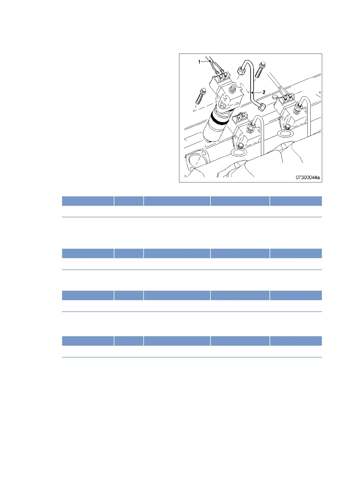
10. Install fuel line (2).
11. Tighten union nut on the injection pump to the specified tightening torque using a torque wrench.
• Maximum permissible tightening torque: 35 Nm
Name Size Type Lubricant Value/Standard
Union nut Tightening torque 20 Nm + 5 Nm
12. Tighten union nut on the pressure pipe neck to the specified tightening torque using a torque wrench.
• Maximum permissible tightening torque: 35 Nm
Name Size Type Lubricant Value/Standard
Union nut Tightening torque 20 Nm + 5 Nm
13. Install injection pump cabling (1).
14. Use torque wrench to tighten screws to the specified tightening torque.
Name Size Type Lubricant Value/Standard
Screw Tightening torque 1.0 Nm ± 0.2 Nm
Final steps
1. Remove barring device (→ Page 76).
2. Clean mating faces on cylinder head and charge-air pipe.
3. Check seals for damage and replace them, if required.
4. Coat seals with grease (Kluthe Hakuform 30-10/Emulgier) and place onto cylinder head.
5. Install charge-air pipes.
6. Install engine control system (→ Page 151).
7. Open fuel supply line before fuel filter.
8. Vent fuel system (→ Page 102).
92 | Task Description | MW15407/14E 2012-02
TIM-ID: 0000004579 - 004