The document is an installation and operation manual for Bakery Chillers, specifically models PMC 40/50 and PMC 70/120, manufactured by Paul Mueller Company.
Function Description
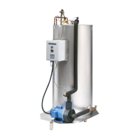
The Mueller bakery chillers are designed to provide chilled water at a preset temperature for batch applications in bakeries. The system maintains the water level in the storage tank after each batch of chilled water is drawn, preventing temperature blending of warmer make-up water with chilled water during the draw.
Important Technical Specifications
Models and Capacities:
- PMC 40/50: Nominal 50-gallon storage capacity, designed for use with a 2 horsepower (HP) condensing unit.
- PMC 70/120: Nominal 120-gallon storage capacity, designed for use with a 3.5 HP condensing unit.
Dimensions and Weight:
| Model |
Width |
Depth |
Height |
Approximate Shipping Weight |
| PMC 40/50 |
32" |
24" |
72" |
310 lb |
| PMC 70/120 |
42" |
34" |
84" |
705 lb |
Refrigeration Components:
- Thermal expansion valve (TEV) for refrigerant control.
- Stainless steel evaporator located outside a baked, glass-lined water tank.
- Inner-connect refrigerant piping with single-point connections for ease of installation.
- Refrigerant: R-507, a Class II HFC binary mixture (50% R-125 and 50% R-143a), classified as "A-1" by ASHRAE Standard 34.
Liquid Solution Flow Components:
- Baked, glass-lined, and insulated water storage tank.
- Water solenoid valve for make-up water control and recirculation.
- Circulation pump.
- Inner-connect piping with single-point 3/4" MPT connections for water inlet and chilled water outlet.
- Supply water line: Minimum 3/4" in size, connected to a 3/4" inlet water solenoid valve.
- Chilled water supply: Connected to a 3/4" chilled water outlet.
Electrical Components:
- Control box with fuses for system protection.
- Electronic temperature control for setting chilled water temperature and displaying temperature in Fahrenheit or Celsius.
- Wiring must comply with the National Electric Code and local regulations.
- Power supply: 230VAC for the main power.
- Transformer: 208-240V PRM, 24V Second, 40VA.
- Pump motor: 3/4 HP, 6.1 FLA, 230VAC/60HZ.
- Temperature sensor: Type "T" thermocouple.
Condensing Unit Specifications (PMC 40/50 with 2 HP Unit):
- Part No. 943711, Unit Model No. FFAP-017Z.
- Overall Dimensions: Length 24.1", Width 18.3", Height 16.6".
- Liquid Line Valve: 3/8 SWT.
- Suction Line Valve: 7/8 SWT.
- Approximate Shipping Weight: 140 lb.
- Compressor Model No.: ZS11KAE.
- Electrical Data (208-230/1/60): M/C Ampere 17.2, Maximum Fuse 25.
- Suitable for outdoor operation with low-ambient controls and weather protection.
Condensing Unit Specifications (PMC 70/120 with 3.5 HP Unit):
- Unit Model No. OESE-A351 (208-230/1/60) or OESE-A353 (208-230/3/60).
- Overall Dimensions: Length 40.1", Width 30.4", Height 31.5".
- Liquid Line Valve: 3/8 SWT.
- Suction Line Valve: 7/8 SWT.
- Approximate Shipping Weight: 358 lb.
- Compressor Model No.: ZB26KC-PFV (for OESE-A351) or ZB26KC-TF5 (for OESE-A353).
- Electrical Data (OESE-A351, 208-230/1/60): M/C Ampere 27.4, Maximum Fuse 45.
- Electrical Data (OESE-A353, 208-230/3/60): M/C Ampere 19.3, Maximum Fuse 30.
Usage Features
Installation:
- Requires installation by an authorized service technician certified in refrigerant usage by the U.S. Environmental Protection Agency (EPA).
- All electrical connections must be performed by a qualified electrician.
- Location: Indoors, protected from freezing temperatures, with accessible circulating pump and control panel. Close to a drain for service and cleaning. Condensing unit (for RC models) must be protected from the environment and have adequate airflow. Locate as close as possible to the point of use for chilled water.
- Refrigerant Piping: Liquid line 3/8" OD copper pipe, suction line 7/8" OD copper pipe. Liquid line drier required for PMC 40/50 RC and RS models (provided on 3.5 HP units for PMC 70/120 RC and RS models). Liquid line sight glass installed just prior to the TEV. TEV sensing bulb attached to the suction line and insulated.
- Evacuation and Charging: System must be evacuated to 500 microns and hold 1,000 microns in a standing vacuum test. Initial refrigerant charging through the liquid service valve (for blended refrigerants).
Operation:
- Power On Sequence (OFF position): Temperature controller powered, displays temperature (may not be true tank temperature if pump is off). All other functions disabled.
- Power On Sequence (ON position): System light on. Fill solenoid fills tank until level switch stops it. Circulation pump on (must be disabled on initial startup or when tank is empty to prevent dry running). Water flows through chiller recirculation loop. Condensing unit operates if water temperature is above setpoint.
- Batch Draw: Process flow switch opens, disabling fill solenoid and condensing unit, closing recirculation solenoid.
- Batch Draw Complete: Process flow switch closes, fill solenoid refills tank. Temperature controller regains control of condensing unit.
Temperature Control:
- Electronic temperature control allows setting desired chilled water temperature.
- Temperature can be displayed in Fahrenheit or Celsius.
- Setpoint can be changed via the "SEL" key and up/down keys.
- Calibration offset can be adjusted to match actual water temperature.
- Units of measure (Fahrenheit or Celsius) can be changed.
Maintenance Features
First Time Startup and Cleaning:
- Ensure water, refrigeration, and electrical piping are complete.
- Open supply water shut-off valve(s) and drain valve.
- Disable circulation pump via toggle switch in control box.
- Turn on power to control panel (condensing unit power off). Push green button to fill tank and allow water to flow until clean from drain.
- Close drain valve, allow tank to fill.
- Enable circulation pump, run for two minutes, then turn off.
- Drain water again; repeat if not clean.
- Filling the System: Close drain valve, disable pump, turn on push-button switch to fill. Open chilled water valve until clean, then close. Allow tank to refill. Enable circulation pump.
- Complete initial condensing unit charging and TEV superheat adjustment.
Troubleshooting:
- Error Message "uuuu": Indicates a disconnected or broken temperature sensor wire, requiring service.
- Fuse Failure: Requires troubleshooting to determine cause and replacement with same fuses.
Thermal Expansion Valve (TEV) Superheat Adjustment:
- Performed with water tank full and water temperature below 40°F.
- Requires accurate suction pressure at evaporator outlet (not service valve) and suction line temperature near TEV sensing bulb.
- Calculate superheat by subtracting saturation temperature (from pressure-temperature chart) from actual suction line temperature.
- Adjust TEV stem clockwise (1/8 to 1/4 turn) if superheat is below 8°F, or counterclockwise if above 10°F. Allow five minutes for system to operate before retesting.
- Check refrigerant charge after TEV adjustment. Add liquid refrigerant slowly to avoid compressor damage.
- Final adjustments made at product temperature near setpoint for best performance.
Warranty:
- One-Year Parts Warranty: Covers defects in workmanship or material under normal use for one year from installation or 18 months from shipment, whichever comes first. Covers replacement or repair of parts.
- Five-Year Structural Warranty: Covers Mueller bakery chiller evaporator (cooling plate) and water storage tank for five years from installation or 66 months from shipment, whichever comes first. Limited to repair or replacement. Does not cover freezing damage.
- Claim Procedures: Requires Return Goods Authorization (RGA) number from Company's Refrigeration Products Department.
- General Provisions: Does not cover refrigerant, transportation, mileage, freight, product loss, cost of substitute storage facilities, parts and labor charged by others, or consumable items. Does not cover abuse, misuse, negligence, improper installation, alterations by unauthorized service, or acts of God. Applies only to original purchaser-user and installation location. Effective in continental United States and Canada.